


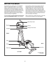

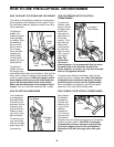
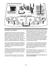
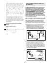
INSTALLING THE RECEIVER FOR THE OPTIONAL CHEST PULSE SENSOR
If you purchase the optional chest pulse sensor (refer to page 19), follow the steps below to install the receiver
and the short jumper wire included with the chest pulse sensor.
1. Remove the two short screws and the two long screws
from the back of the Console (23). Lift off the front of
the Console.
2. Plug the short jumper wire (A) into the indicated jack on
the Console (23). Connect the other end of the short
jumper wire to the wire on the receiver (B). Note: Any
other wires included with the chest pulse sensor can be
discarded.
Next, peel the paper off the adhesive pad on the back
of the receiver (B). Orient the receiver as shown, and
press it onto the Console (23) in the indicated location.
Refer to step 1 above. Reattach the front of the
Console (23) with the short and long screws. Make
sure that no wires are pinched.
8
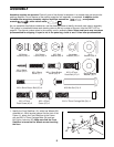
10. Make sure that all parts of the elliptical crosstrainer are properly tightened. Note: Some hardware may
be left over after assembly is completed. To protect the floor or carpet from damage, place a mat under the
elliptical crosstrainer.
B
23
Jack
23
Short
Screws
Long
Screws
Lift
Here
1
A
Cylinder
2
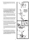
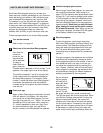
9. Apply a small amount of grease to the axle on the left
Disc Crossbar (16). Slide a Spring Spacer (63) and the
Left Rear Spring Bracket (12) on the left Pedal Spring
(11) onto the axle. Next, slide a Spring Bracket Washer
(35) onto an M10 x 27mm Patch Screw (40), and tight-
en the Patch Screw into the axle.
Next, hold the lower end of the Handlebar Leg (5)
inside of the Front Spring Bracket (76) on the left Pedal
Spring (11). Apply grease to an M10 Bolt Set (74).
Attach the Handlebar Leg to the Front Spring Bracket
(76) with the Bolt Set. Do not overtighten the Bolt
Set; the Left Handlebar must be able to pivot freely.
Attach the right Pedal Spring (not shown) to the right
side of the elliptical crosstrainer in the same way.
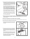
Tighten the M6 x 25mm Screw (7) into the Upright (2).
Turn the Upright Knob (43) clockwise until it is tight.
Refer to step 7. Tighten the M8 x 45mm Button Bolts
(50) in the Handlebar Legs (5).
Grease
Grease
16
74
11
11
9
40
35
63
12
74
5
43
7
2
76