


Page 5For technical questions, please call 1-800-444-3353.SKU 98579
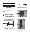
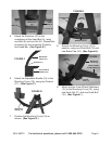
FIGURE E
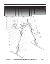
BOLT (8)
NUT (9)
PROTECTOR
(22)
HEAD
BAR (6)
5. Attach the Protector (22) to the
crossbeam of the Head Bar (6), using
one Bolt (8) and one Nut (9). Repeat this
procedure for the remaining Protector
and Head Bar. (See Figure E.)
FIGURE F
MOUNTING
CURVE (10)
SCREWS (17)
ADJUSTABLE
SADDLE (18)
6. Attach the Adjustable Saddle (18) to the
Mounting Curve (10), using two Screws
(17). (See Figure F.)
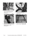
FIGURE G
MOUNTING
CURVE (10)
7. Position the Mounting Curve (10) as
shown. (See Figure G.)
FIGURE H
KNOB
BOLT (16)
BRAKE CAP (24)
CONNECTOR
(23)
8. Secure the Mounting Curve (10) in
position, using one Knob Bolt (16) and
one Brake Cap (24). (See Figure H.)
FIGURE I
KNOB
BOLT (16)
KNOB
NUT (11)
FRONT WHEEL
STABILIZERS (15)
MOUNTING
CURVE (10)
9. Attach the two Front Wheel Stabilizers
(15) to the Mounting Curve (10), using
one Knob Nut (11) and one Knob Bolt
(16). (See Figure I.)