


3
5
1
2
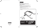
REFER TO
APPLICATION
GUIDE
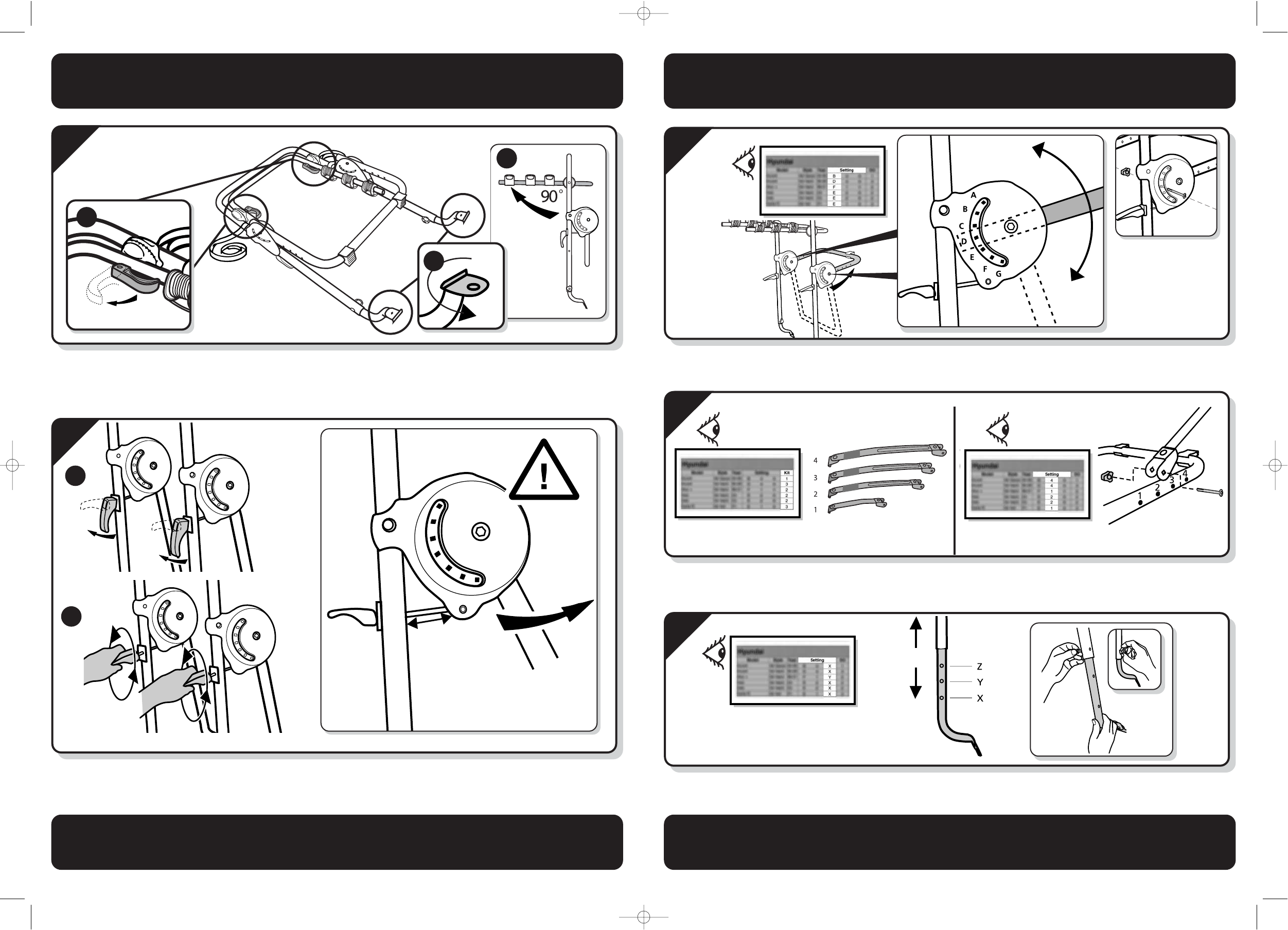
Adjuster Plate
1
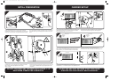
Position the assembled carrier on a clean surface as illustrated.
(1) Release the 2 adjuster levers and (2) rotate the cycle support arms
through 90º and lock in position. The quick release action should be
firm for both opening and closing. The tension may be set by releasing
the handles and turning clockwise. (3) Rotate the bottom feet 180º as
shown.
(1) Release the two carrier clamping levers and (2) turn the handles
anti-clockwise until the angle adjusters are fully opened,
(approx 40 turns).
Rotate the large black angle adjusters upwards, ensuring a minimum of
45mm of screw is visible between the angle adjusters and the main
carrier frame.
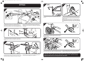
Refer to the enclosed application list to find the correct angle for the
vehicle support arm for your car. Insert the bolts from the outside
faces in the specified holes A, B, C, D, E, F or G.
Fit the thumb screw nuts to the inside face of the angle adjusters,
making sure the bolt passes through the vehicle support arm.
Refer to the enclosed application list to find the correct metal strap for
your car. Refer to the enclosed application list to find the correct
clamp bolt hole for your car. Insert the bolts, from the outer faces,
through the metal clamps and the vehicle support arm.
Fit the thumb screw nuts on the inside of the vehicle support arm.
Refer to the enclosed application list to find the correct position for the
extendible feet X, Y or Z. Insert the bolts from the outside faces, fit the
thumb screw nuts to the inside of the carrier frame.
2
45mm
INITIAL PREPARATION CARRIER SET-UP
DO NOT PROCEED ANY FURTHER UNTIL STEPS 1 + 2
HAVE BEEN COMPLETED CORRECTLY
DO NOT USE ANY HOLE SETTINGS OTHER THAN THOSE
SPECIFIED FOR YOUR VEHICLE MAKE AND MODEL.
4
REFER TO
APPLICATION
GUIDE
Strap Location
180°
1
2
3
REFER TO
APPLICATION
GUIDE
Strap Selection
REFER TO
APPLICATION
GUIDE
Lower Mount
Halfords hi 3 bike instructions 6/8/07 12:05 PM Page 3