


3
2
1
3
1
2
1
4
4
1
PART LIST/EXPLODED DRAWING— R1005A
Model No. GGMC0622.0
3
1 4 17.5mm Spacer
2 4 Resistance Rod
3
2
Exterior Band
4 2 Clip
# 1 Resistance Decal
# 1 User’s Manual
Note: “#” indicates a non-illustrated part.
Specifications are subject to change without notice.
Key No. Qty. Description
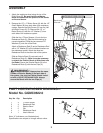
ASSEMBLY
E
Bands on
t
his end
1
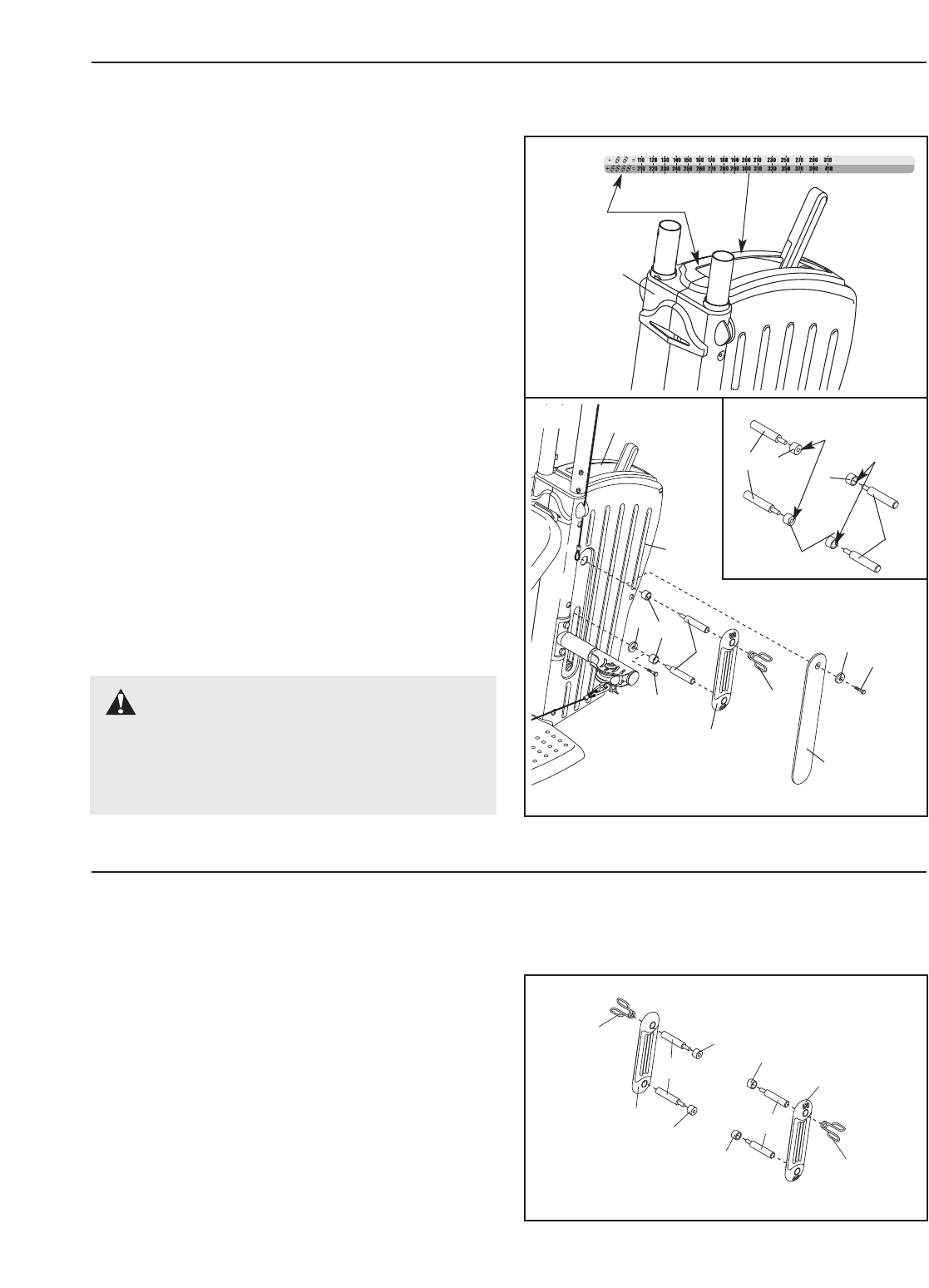
1. Attach the resistance decal along the top of the
Right Cover (E).
Be sure that the resistance
decal is oriented with the pictures of the bands
o
n the end shown.
2. Remove the 1/2” x 1” Button Screw (A) with the 1/2”
Small Washer (B) from each side of the resistance
system. Remove the Side Covers (C) from the Left
and Right Covers (D, E). Remove the 1/2” x 1”
Button Screw (A) with the 1/2” Washer (F) from
each side of the resistance system.
Slide the four 17.5mm Spacers (1) onto the four
Resistance Rods (2). (See the inset drawing for
correct orientation.) Slide the two removed 1/2”
Washers (F) onto two of the Rods.
Attach a Resistance Rod (2) and a Resistance Rod
with a 1/2” Washer (F) to the indicated locations on
the resistance system. Attach the other two
Resistance Rods to the other side of the system.
Slide an Exterior Band (3) onto each set of
Resistance Rods (2). (
Note: It may be necessary
to stretch the Exterior Bands to slide them onto
the Rods.) Secure the Exterior Bands (3) to the
Resistance Rods (2) with the two Clips (4).
WARNING: Always place the same
number of Exterior Bands (3) on each side of
the system. Use only the Exterior Bands includ-
ed with a GOLD’S GYM MAX PACK. Always
secure the Bands with the two Clips (4).
2
3
4
2
1
C
D
F
B
A
A
E
Small
Hole
Large
Hole
1
1
2
2
1