10
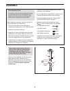
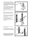
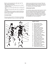
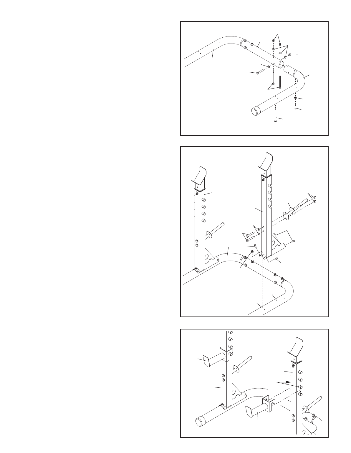
11. Identify the Left Upright Base (39), which is
marked with an L sticker. Attach a Foot (39) to
t
he Left Upright Base with an M5 x 19mm Screw
(50). Insert an M10 x 90mm Carriage Bolt (40) up
i
nto the Left Upright Base. N
ote: It may be help-
ful to place a piece of tape over the bolt head
to hold it in place.
Attach the Left Upright Base (9) to the Base (7)
with two M10 x 90mm Carriage Bolts (40), an
M10 x 90mm Bolt (42), four M10 Washers (52),
and three M10 Nylon Locknuts (57).
Do not
tighten the Nylon Locknuts yet.
Repeat this step for the Right Upright Base
(10).
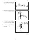
12. Attach a Storage Tube (14) to an Upright (11)
with two M10 x 90mm Bolts (42), two M10
W
ashers (52), and two M10 Nylon Locknuts
(57).
Attach the Upright (11) to the Left Upright Base
(9) with the M10 x 90mm Carriage Bolt (40),
four M5 x 19mm Screws (50), and an M10
Nylon Locknut (57).
Repeat this step for the other Upright (11)
and the Right Upright Base (10).
See step 11. Tighten all of the M10 Nylon
Locknuts (57).
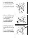
13.
Set a Safety Spotter (13) on a set of pegs on
the left Upright (1
1).
Set the other Safety Spotter (13) on a set of
pegs on the right Upright (1
1).
Make sure that
both Safety Spotters are at the same height.
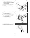
14. Make sure that all parts are properly tight-
ened before you use the weight bench. The
use of all remaining parts will be explained
in
ADJUSTMENT on pages 1
1 and 12.
11
12
13
9
1
0
4
2
40
39
50
40
52
5
2
57
57
7
57
14
50
50
40
9
50
57
42
52
11
11
10
13
1
1
Pegs
13
11


