


66
5
14
9
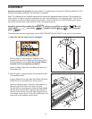
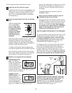
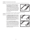
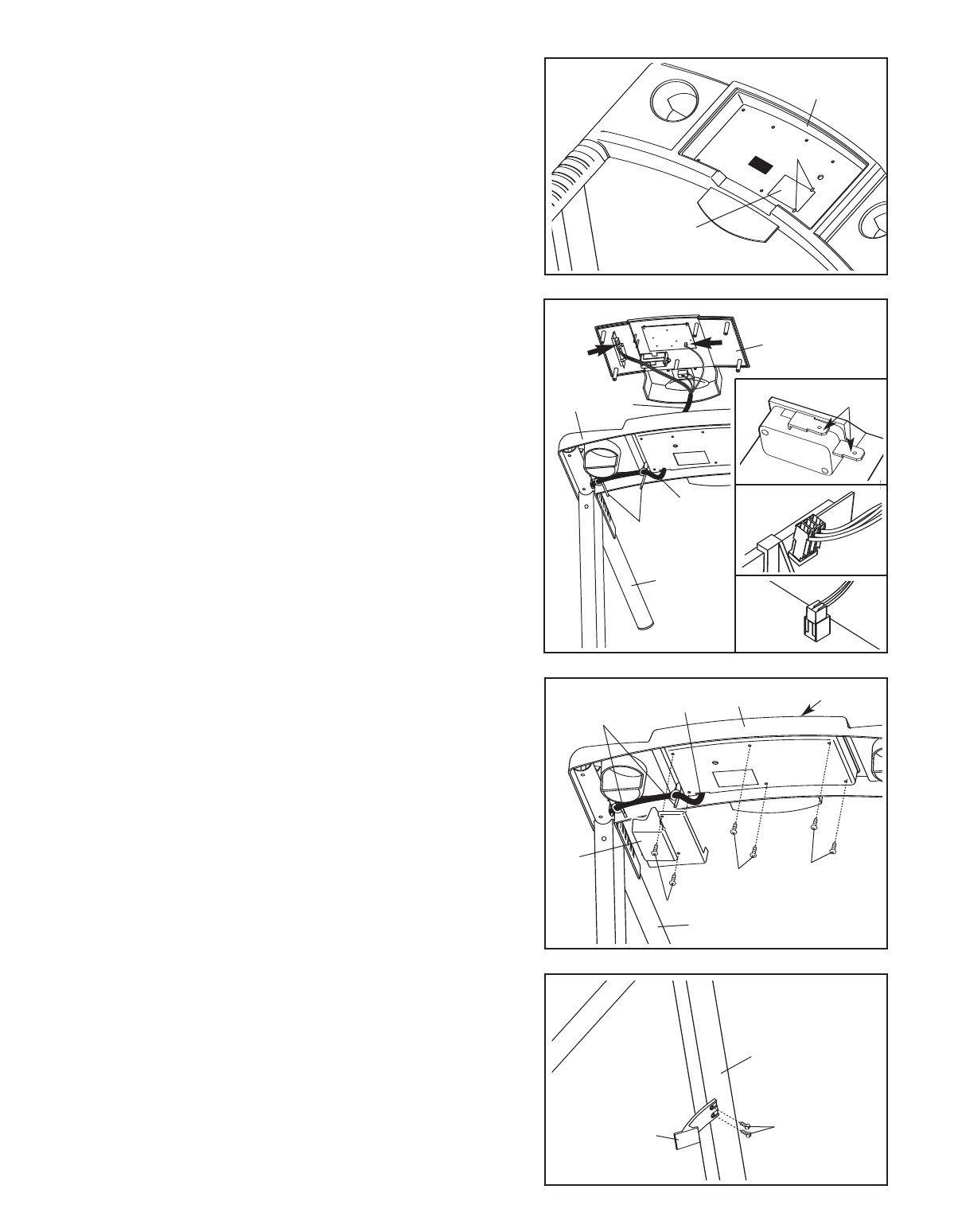
9. Attach the Storage Latch (66) to the left Upright (14)
with two 3/4” Screws (5).
10.Make sure that all parts used in assembly are prop
-
erly tightened before you use the treadmill. Keep the
included allen wrench in a secure place. The allen
wrench is used to adjust the walking belt (see page 13).
T
o protect the floor or carpet, place a mat under the
treadmill.
8
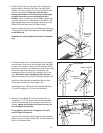
8. Set the Console (11) in the Console Base (87). Make
sure that no wires are pinched. Insert as much of the
Wire Harness as possible (53) down the hole in the
Right Handrail (94). Securely tighten the plastic tie
nearest the Right Handrail. Pull any excess Wire
Harness between the plastic ties tight and tighten the
other plastic tie. Cut off the ends of the plastic ties.
Cover the Wire Harness with the Wire Cover (10), and
route the Wire Harness out of the hole in the side of the
Wire Cover. Attach the Wire Cover to the back of the
Console Base with two 3/4” Screws (5).
Do not over-
tighten the Screws.
Make sure that no wires are pinched before you attach
the Console (1
1) to the Console Base (87). T
ighten the
remaining four 3/4” Screws (5) into the Console Base and
the Console. Do not overtighten the Screws.
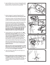
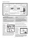
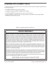
7. Hold the Console (11) near the Console Base (87).
Touch the Right Handrail (94) to discharge any static.
Locate the two wires in the Wire Harness (53) that have
L-shaped connectors on the ends. Press the connectors
onto the two tabs on the switch shown in inset drawing 7a.
Connect the other two wires in the Wire Harness (53) to
the back of the Console Base (87) in the locations
shown by the arrows in drawing 7.
The connectors
should slide easily into the sockets and snap into
place (see drawings 7b and 7c). If the connectors do not
slide easily and snap into place, turn the connectors and
then insert them. IF THE CONNECTORS ARE NOT
INSERTED PROPERLY, THE CONSOLE MAY BE
DAMAGED WHEN THE POWER IS TURNED ON.
11
53
53
7
87
7
Ties
94
12
Hinges
8
7
6
6. Insert the Battery Cover (12) into the Console Base (87),
with the hinges in the position shown. The Battery Cover
s
hould pivot down, away from the Console Base.
7a
Tabs
7c
7b
87
53
10
5
94
5
5
11
Ties