


The information in this manual furnished for information use only, is subject to change without notice, is not to be
construed as a commitment by ATN Corp.
ATN Corp. assumes no responsibility or liability for any errors or inaccuracies that may appear in this book.
©2002 ATN Corp. All right reserved.
2
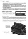
APPLICATION
The Aries MK6600/6650/7700/7750/8700/8750 night vision weapon scope is a complex computer-
ized system for the observation of objects at low light levels. Containing an onboard computer these
scopes are some of the most advanced night vision weapon scopes in the world.
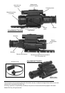
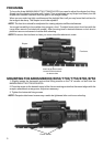
The Aries MK6600/6650/7700/7750/8700/8750 consists of the objective lens assembly, ocular
lens assembly and the body. The body contains the image intensifier tube assembly with the inte-
grated high voltage power source. The body also houses the electronics for the reticle, the computer
console for the “Smart Technology” as well as the battery compartment. The 100M infra-red illumi-
nator is located on the top of the unit.
The objective lens protective cover (not shown) is designed to protect the lens from scratches and
abrasions. This cover also protects the image intensifier tube from exposure to daylight or other
bright light sources. The protective cover acts as a daylight filter, note the pinhole in the center of
the lens cap.
MASTER POWER SWITCH
The Master ON/OFF switch is to be found on top of
MK6600/6650/7700/7750/8700/8750. Once the
scope’s master power is switched on you can adjust
the scope using the buttons on the control box.
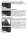
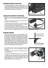
CONTROL PANEL
The control box with the cluster of three buttons on it can be found on the left side of the Aries
MK6600/6650/7700/7750/8700/8750. ”SL” button acts as a three-way selection toggle. By press-
ing it once you will see one of three colored diodes located on the rear side of the control box light
up. Make sure to keep both eyes open; your right eye is expected to aim through the scope so that
your left eye perceives the changes on the rear side of the control box. “+” and “-” buttons are used
to correspondingly increase or decrease adjustments for a chosen function.
The three colored led diodes represent the scope function mode. “B” stands for brightness of the
light intensifier tube, “R”- for reticle brightness, and “I”- for IR illuminator brightness.
Brightness LED
Reticle brightness LED
Illuminator brightness LED
“+” adjustment button
“-” adjustment button
“SL” selection button
Master power switch