


MK-DVF-HID
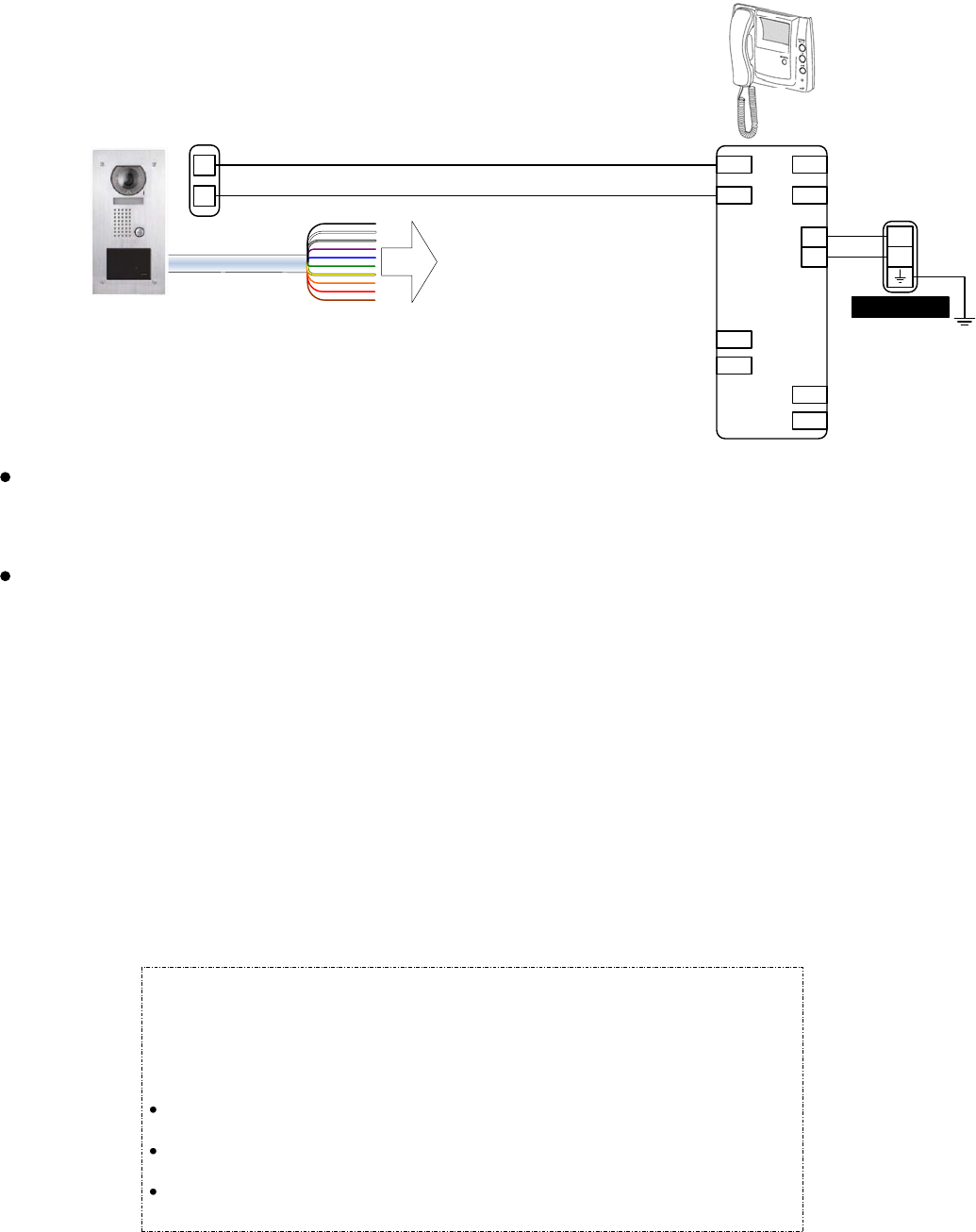
PS-1820UL
+
-
A1
A2
Output to Host
Access Control System
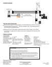
WIRING DIAGRAM:
TESTING AND OPERATION:
When power is applied to the card reader, the LED will flash green three (3) times while
the beeper beeps simultaneously. The LED will then turn red. This indicates that the
microcontroller is operating properly.
Present an ID card to the reader. (Hold card directly in front of reader.) The LED will
momentarily turn green while the beeper beeps once, indicating that the card was read
successfully.
CARD READER:
Power Source: 5 ~ 16V DC
Absolute Max. Voltage: 18V DC
Current Requirements: 30mA (Avg); 75mA (peak)
Terminations: Color-coded pre-wired pigtail
Wiring Distance: 500'
Operating Temperature: -10°~60°C / 14°~140°F
Operating Humidity: 0-95% relative humidity
non-condensing
SPECIFICATIONS:
CAMERA:
Camera unit: CCD Camera
Scanning line: 525 lines
Min. illumination: 1 Lux at 1'
Terminations: Screw terminals
Wiring Distance: 330' w/871802 wire
980' w/MYW-BA & 851602 wire
Dimensions(camera): 5-¾” W x 11-⅝” H x 1-5/16" D
With SBX-DVF-P: 5-15/16" W x 11-¾” H x 2-13/16" D (Top)
1-15/16" D (Bottom)
Aiphone Communication Systems
1700 130th Ave. N.E.
Bellevue, WA 98005
(425) 455-0510
FAX (425) 455-0071
Toll Free Technical Support:
1-800-692-0200
E-mail tech-serv@aiphone.com
Pg. 2
MK-DVF-HID Instr.
0706JDJS
FCC WARNING:
This device complies with Part 15 of the FCC rules.
Operation is subject to the following two conditions:
(1) This device may not cause harmful interference.
(2) This device must accept any interference that may cause undesired operation.
For proper regulatory compliance, the drain wire should be disconnected at the
power supply end of the cable.
Changes or modifications not expressly approved by the party responsible for
compliance could void the user’s authority to operate the equipment.
The Reader is intended to be powered from a limited power source output of a
previously certified power supply.
MK-1GD
1A1
1A2
B1
B2
+
-
S
S
L
L