


SECTION 2
INSTALLATION
15
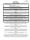
V. GAS SUPPLY
CAUTION
DURING PRESSURE TESTING NOTE THE FOLLOWING:
1. The oven and its individual shutoff valve must be dis-
connected from the gas supply piping system during any
pressure testing of that system at test pressure in excess
of 1/2 psi (3.45 kPa).
2. The oven must be isolated from the gas supply piping
system by closing its individual manual shutoff valve dur-
ing any pressure testing of the gas supply piping system
at test pressure equal to or less than 1/2 psi (3.45 kPa).
3. If incoming pressure is over 14" W.C. (35mbar), a sepa-
rate regulator MUST be installed in the line BEFORE the
individual shutoff valve for the oven.
WARNING:To prevent damage to the control valve regu-
lator during initial turn- on of gas, it is very important to
open the manual shutoff valve very slowly.
After the initial gas turn-on, the manual shutoff valve must
remain open except during pressure testing as outlined
in the above steps or when necessary during service
maintenance.
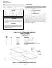
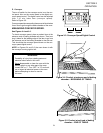
A. Gas Utility Rough-In Recommendations
The following gas system specifications are STRONGLY
RECOMMENDED. Deviating from these recommendations may
affect the baking performance of the oven.
Gas Meter - 650 cfh (307/min) meter
Gas Line
• DEDICATEDLINEfromthegasmetertotheoven
• 2"(50.8mm)pipefornaturalgas
• 1-1/2"(38.1mm)pipeforpropane
• Maximumlength:200'(61m).Each90°elbowequals7'
(2.13m) of pipe.
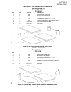
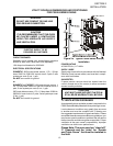
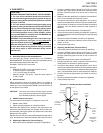
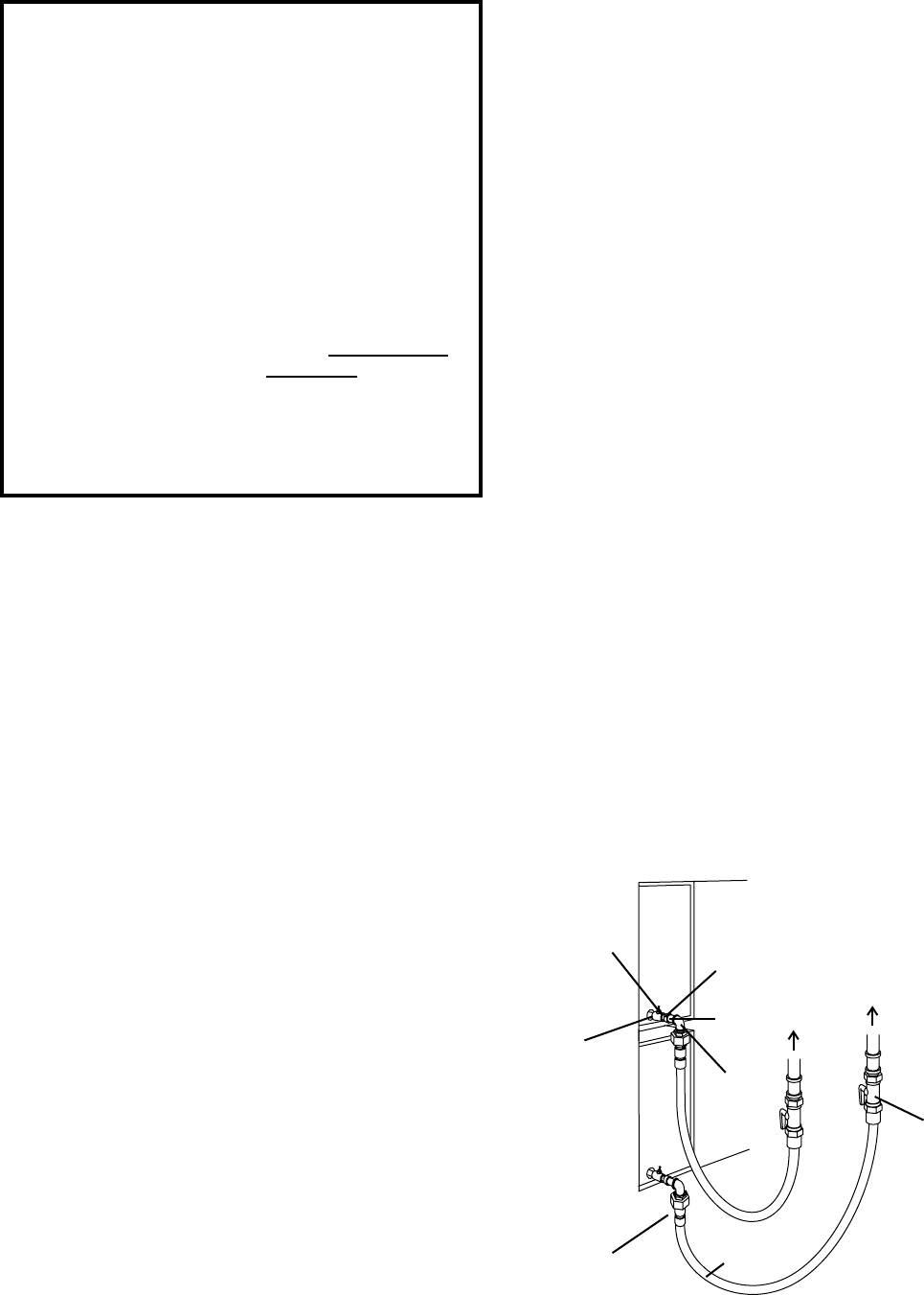
Figure 2-15 - Flexible Gas Hose Installation
B. Gas Conversion
Where permitted by local and national codes, it is possible to
convert ovens from natural to propane gas, or from propane to
natural gas. Use the appropriate Middleby Gas Conversion Kit
forthespecicovenmodel.
CAUTION: The terms of the oven’s warranty require all start-
ups, conversions and service work to be performed
by a Middleby Authorized Service Agent.
C. PS520 Propane Conversion
Twoitemshavetobechanged,tochangetheoventoLP:
1. Replacemainorices.
2. Adjust main gas regulator per instructions below.
Disconnect the manifold union closest to the main burner, and
remove the manifold assembly (four screws). Slide out the mani-
fold assembly (leaving the ignition and sense wires connected).
Replacethemainorices.
ReplacethemainoricesonthemanifoldassemblieswiththeLP
units, and replace the manifold assembly. Reconnect the union.
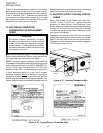
D. Adjusting the Maximum Pressure Setting
1. Disconnect pressure feedback connection (if applicable).
2. Connect a suitable pressure gauge to pipe line or to outlet
pressure tap of gas control concerned, to measure burner
pressure (measuring point must be as near to burner as
possible).
3. Make sure that the appliance is in operation and the Modu-
plus
®
coilisenergizedwithmaximumcurrent.
4. Ifmaximumratepressureneedsadjustment,usean8mm
wrenchtoturnadjustmentscrewformaximumpressureset-
ting (clockwise to increase or counter-clockwise to decrease
pressure), until the desired maximum outlet pressure is
obtained.
5. Disconnect electrical connection of the Moduplus
®
.
6. Check minimum pressure setting and readjust if necessary.
(See Adjusting Minimum Pressure Setting for proper adjusting
procedure.)
7. Reconnect pressure feedback connection (if appcable).
8. Ifminimumandmaximumpressuresareset,wiretheMo-
duplus
®
in circuit.
9. Close pressure tap screw.
E. Adjusting the Minimum Pressure Setting
1. Disconnect pressure feedback connection (if appcable).
2. Connect a suitable pressure gauge to pipe line or to outlet
pressure tap of gas control concerned, to measure burner
pressure (measuring point must be as near to burner as
possible).
3. Disconnect electrical connection of the Moduplus
®
.
4. Energize operator, set control in operation and wait until an
outlet pressure is recorded on pressure gauge.
5. If minimum rate pressure needs adjustment, use an 8 mm
wrench to turn adjustment screw for minimum pressure setting
(clockwise to increase or counter-clockwise to decrease pres-
sure), until the desired minimum outlet pressure is obtained.
6. Check if main burner lights easily and reliable at minimum
pressure.
7. Reconnect pressure feedback connection (if appcable).
8. Close pressure tap screw.
To Gas
Supply
Pipe
90°
Elbow
Quick-
disconnect
device
Flexible
Gas Hose
Full-Flow
Gas
Shutoff
Valve
3/4"gas
pipe nipple
3/4"-1/2"
gas pipe
reducer
Individual gas
connection
for each oven
cavity
1/2"gas
pipe nipple
1/2"gas
line tee with
pressure tap