29
2
INSTALLATION AND WIRING
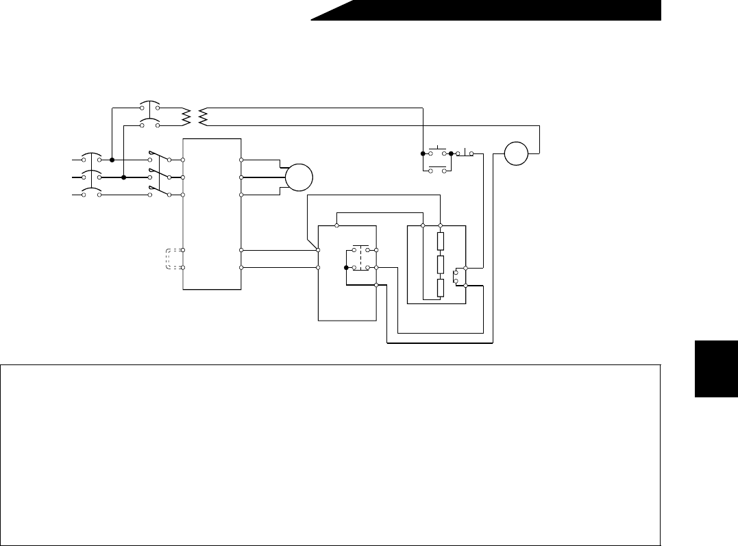
(2) Connection of the brake unit (FR-BU)
Connect the optional FR-BU brake unit as shown below to improve the braking capability during deceleration.
Note: 1. Connect the inverter terminals (P, N) and FR-BU brake unit terminals so that their terminal signals
match with each other. (Incorrect connection will damage the inverter.) For model 7.5K or less,
the jumper across terminals PR-PX must be removed.
2. The wiring distance between the inverter, brake unit and resistor unit should be within 5m. If
twisted wires are used, the distance should be within 10m.
3. When the transistor in the brake unit fails, the brake transistor bacomes extremely hot and it has
a chance to get fire. Therefore, install a magnetic contactor on the inverter's power supply side to
shut off a current in case of failure.
4. For the power supply of 400V class, install a voltage-reducing transformer.
MC
U
V
W
P/+
N/–
PR
PX
IM
PR
P/+
N/-
HA
HB
HC
Brake unit
FR-BU-(H)
Resistor unit
FR-BR-(H)
THS TH2
Normal : TH1 - TH2....close
PPR
ON
MC
OFF
MC
Remove jumper.
Inverter
Motor
T (Note 4)
Alarm : TH1 - TH2....open
TH1
ower
upply
R
S
T


