


11
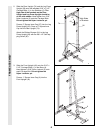
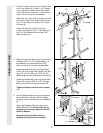
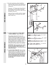
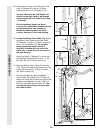
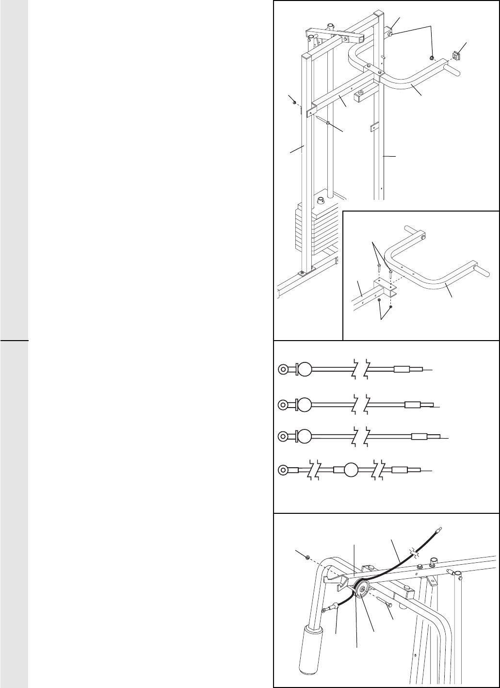
15. See the inset drawing. Attach the Military
Press Arm (84) to the Pivot Arm (80) with two
5/16Ó x 2 1/4Ó Bolts (33) and two 5/16Ó Nylon
Locknuts (3).
Press two 1 1/2Ó Square Inner Caps (32) into
the indicated end of the Military Press Arm
(84). Press two 1Ó Round Inner Caps (49) into
the Military Press Arm.
Attach the Pivot Arm (80) to the Rear Upright
(74) with a 3/8Ó x 3 1/4Ó Bolt (67) and a 3/8Ó
Nylon Locknut (21).
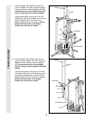
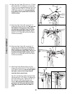
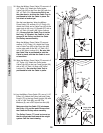
16. Locate and open the parts bags labeled
ÒCABLE ASSEMBLYÓ and ÒPULLEYS.Ó
During steps 16 through 36, refer to the
CABLE DIAGRAMS on pages 25Ð26 of this
manual to verify proper cable routing. Before
beginning this section, fully unwind the four
Cables. Identify the four Cables by comparing
the lengths and ends of the Cables. The
approximate length of each Cable is listed (in
inches) after the key number in the drawing.
IMPORTANT: While assembling the cables,
do not over tighten the bolts and nuts
attaching the pulleys. The pulleys must be
able to turn freely.
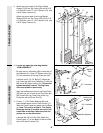
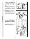
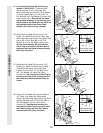
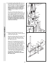
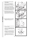
17. Locate the High Cable (58). Wrap the High
Cable around a 3 1/2Ó Pulley (15). Attach the
Pulley to the Top Frame (55) with a 3/8Ó x
3 3/4Ó Bolt (88) and a 3/8Ó Nylon Locknut (21).
Be sure that the end of the Cable with the
ball is on the indicated side of the Pulley
and that the Cable is between the Pulley
and the hook.
17
55
21
58
Ball
Hook
15
49
32
84
84
80
80
21
67
5674
33
3
16
23Ñ78.25Ó
58Ñ146.25Ó
72Ñ238.5Ó
78Ñ63.375Ó
ARM ASSEMBLYCABLE ASSEMBLY
32
15
88