


D500-07-00 1 I56-432-11R
DH500ACDC Intelligent Air Duct
Smoke Detector Housing
INSTALLATION AND MAINTENANCE INSTRUCTIONS
3825 Ohio Avenue, St. Charles, Illinois 60174
1-800-SENSOR2, FAX: 630-377-6495
www.systemsensor.com
Before Installing
Please thoroughly read the System Sensor Manual I56-
473-XX, Guide for Proper Use of Smoke Detectors in Duct
Applications, which provides detailed information on
detector spacing, placement, zoning, wiring, and special
applications. Copies of this manual are available at no
charge from System Sensor. NFPA Standards 72 and 90A
should also be referenced for detailed information.
NOTICE: This manual should be left with the owner/user
of this equipment.
IMPORTANT: This detector must be tested and maintained
regularly following NFPA 72 requirements. The detector
should be cleaned at least once a year.
Specifications
Length: 14.5 inches (36.7 cm.)
Width: 5 inches (12.7 cm.)
Depth: 4 inches (10.2 cm.)
Weight: 4 lbs. (1.8 kg.)
Operating Temperature Range: 32° to 120°F (0° to 49°C)
Operating Humidity Range: 10% to 93% Relative Humidity
Duct Air Velocity: 500 – 4000 ft./min. (91.4 – 1219.2 m/min.
Power Supply Electrical Ratings For DH500ACDC
The currents shown for the DH500ACDC are maximum values with no accessories.
* All accessory currents are additional to DH500ACDC. There are no additional currents for accessories in standby.
** RTS451/RTS451KEY when the magnet is held in place to initiate an alarm.
24V output maximum load is 80 mA; auxiliary alarm output maximum load is 20 mA.
Auxiliary Relay Contacts
Minimum contact current must be greater than 500 mA at 24 VDC
10 amps maximum at 30 VDC
10 amps maximum at 250 VAC
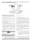
General Description
An HVAC system supplies conditioned air to virtually every
area of a building. Smoke introduced into this air duct sys-
tem will be distributed to the entire building. Smoke detec-
tors designed for use in air duct systems are used to sense
the presence of smoke in the duct.
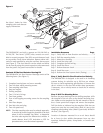
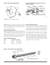
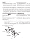
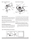
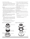
The DH500ACDC Air Duct Detector Housings are used with
System Sensor’s Model 1551 ionization detector heads and
Model 2551 photoelectronic detector heads (purchased sep-
arately). These two smoke detection methods are combined
with an efficient housing design that samples air passing
through a duct and allows detection of a developing hazard-
ous condition. When sufficient smoke is sensed, an alarm
signal is initiated at the fire control panel monitoring the
detector, and appropriate action can be taken to shut off
fans and blowers, change over air handling systems, etc.
This can prevent the distribution of toxic smoke and fire
gases throughout the areas served by the duct system.
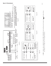
Power 120 VAC (102 - 132) 240 VAC (204 - 264) 24 VAC (20.6 - 26.4)
24 VDC (20 - 30)
Requirements mA rms MAX. mA rms MAX. mA rms MAX.
mA DC MAX.
Device
Standby Alarm Standby Alarm Standby
Alarm Standby Alarm
DH500ACDC
44 52 25
30
65
182 26 87
PA400*
-- 3 --
1.5
--
29 -- 15
RA400ZA*
-- 1.5 --
1 -- 17.3 -- 10
RTS451/RTS451KEY*
-- 1.5 --
1 -- 17.3 -- 10
RTS451**/RTS451KEY
11.5 13 5.5
6.5 140 157 95 103