


D200-54-00 1 I56-710-09
2100D and 2100TD Photoelectronic
Smoke Detectors
INSTALLATION AND MAINTENANCE INSTRUCTIONS
A Division of Pittway
3825 Ohio Avenue, St. Charles, Illinois 60174
1-800-SENSOR2, FAX: 630-377-6495
Before Installing
Please thoroughly read System Sensor manual I56-407,
Guide for Proper Use of System Smoke Detectors, which
provides detailed information on detector spacing, place-
ment, zoning, wiring, and special applications. Copies of
this manual are available at no charge from System Sensor.
NOTICE: This manual should be left with the owner/user
of this equipment.
IMPORTANT: This detector must be tested and maintained
regularly following NFPA 72 requirements. The detector
should be cleaned at least once a year.
General Description
Model 2100D is a 2-wire photoelectronic smoke detector
that uses a state-of-the-art optical sensing chamber. This
detector is designed to provide open area protection and
to be used with compatible UL-listed panels only. Model
2100TD features a restorable, built-in, xed-temperature
(135°F) thermal detector.
Specications
Diameter: 5.5 inches (140 mm)
Height (including mounting bracket): 1.7 inches (43 mm)
Weight: 5.3 oz. (150 g)
Operating Temperature Range: Model 2100D: 32° to 120°F (0° to 50°C)
Model 2100TD: 32° to 100°F (0° to 39°C)
Operating Humidity Range: 10% to 93% Relative Humidity, Noncondensing
Latching Alarm: Reset by momentary power interruption
Heat Sensor (Model 2100TD only): 135°F Fixed Temperature Electronic Thermistor
Electrical Ratings
System Voltage – Nominal: 12 or 24 VDC
Minimum: 8.5 VDC
Maximum: 35 VDC
Maximum Ripple Voltage: 30% of nom. Voltage (peak to peak)
Start-up Capacitance: 0.02 µF maximum
Standby Current: 50 µA maximum
Alarm Ratings: 4.2 VDC minimum at 10 mA.
6.6 VDC maximum at 100 mA.
(Alarm current must be limited to 100 mA maximum by the control panel. If
used, the RA400Z Remote Annunciator operates within the specied detector
alarm currents.)
Reset Voltage: 2.5 VDC minimum
Reset Time: 0.3 seconds maximum
Start-up Time: 30 seconds maximum (after 60 second reset)
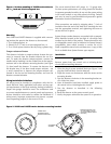
Installation of these detectors is simplied by the use of a
mounting bracket and a plug-in screw terminal block that
can be prewired to the system, allowing the detector to be
easily installed or removed for cleaning. The detector’s
sensitivity can be tested in place using the MOD400R Test
Module. An LED on the detector provides a local visual
indication of the detector’s status. If power is applied to
the detector, and it is functioning normally in standby, the
status LED blinks every ten seconds. The LED also latches
on in alarm.
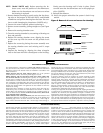
Models 2100D and 2100TD feature a visual indication that
maintenance is required – if the sensing chamber drifts out
of its sensitivity limits, the LED ceases to blink.
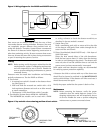
The detectors also include an output that allows an optional
Model RA400Z Remote Annunciator to be connected.