


ASSEMBLY INSTRUCTIONS
8
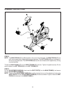
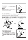
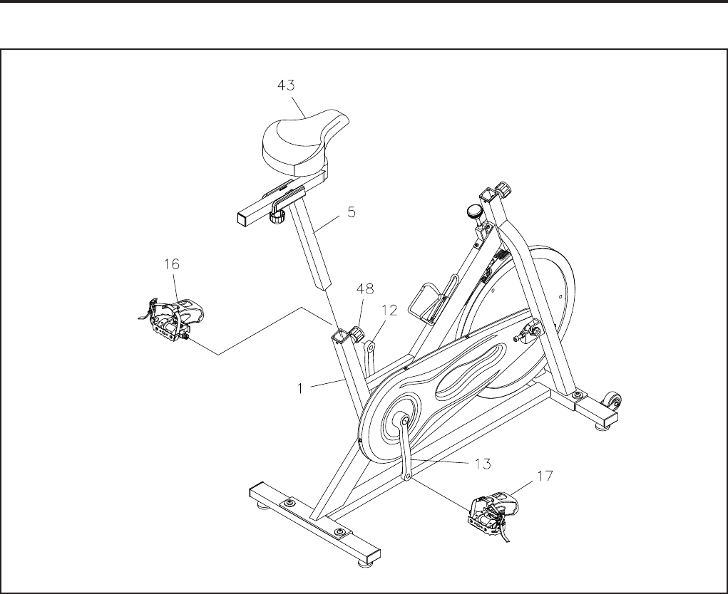
STEP 3
NOTE:
The RIGHT PEDAL(17) has R stamped on the end of the pedal shaft. The RIGHT PEDAL(17) has
right hand threads and is tightened by turning clockwise. The LEFT PEDAL(16) has L stamped on
the end of the pedal shaft. The LEFT PEDAL(16) has left hand threads and is tightened by turning
counterclockwise.
Thread the RIGHT PEDAL(17) into the RIGHT CRANK(13) as shown. Tighten the pedal securely. Do the
same to attach the LEFT PEDAL(16) to the LEFT CRANK(12).
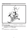
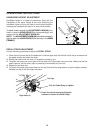
STEP 4
Pull the ADJUSTMENT KNOB(48), then insert the SEAT POST(5) into the MAIN FRAME(1) and secure
with the ADJUSTMENT KNOB(48).
NOTE: The pin of the ADJUSTMENT KNOB(48) should be inserted into one of the adjustment holes in the
SEAT POST(5). And the ADJUSTMENT KNOB(48) should be screwed in tight to make the SEAT
POST(5) fits securely in the MAIN FRAME(1).