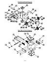
7. Place Side Weight Stack Covers (73) so that the holes on the cover align with the holes on the tabs of the
Upper Frame and bottom Side Base Rails (6,7). Secure with bolts #113, flat washers #136 and nuts #130.
8. Install jam nuts (103) onto threaded portion of each Weight Stack Pulley Bracket (101). Rotate the nut until
¾” of the thread is exposed. Now install Weight Stack Pulley Brackets (101) to the top plate of the weight
stacks (98). Turn each Weight Stack Pulley Bracket until it hits the jam nut (103).
9. Install small, Single-Groove Pulley (33) into each Weight Stack Pulley Bracket (101) and secure each with
bolt #109, flat washer #134 and lock nut #129.
10. Make sure all pulley bolts are tight.
STEP #6 – CABLE INSTALLATION
1. If ball and bracket assemblies are attached to cables, disassemble and set aside.
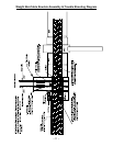
2. Begin by screwing Side Weight Stack Cable (102) into Cable Head Slider Frame (15,16) one-half inch (½”).
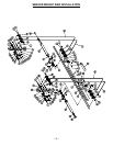
3. For each left and right cable installation perform the following steps: Thread Side Weight Stack Cable (102)
over the two pulleys in the Upper Frame (8,9), then down and underneath the Weight Stack Pulley and back
up over the remaining two Upper Frame pulleys and then down to the pulley on the side Base Rail (6,7).
Next, thread the cable through the holes in the weight stack support frame on the lower base rails, then
underneath the pulley in the Front Guide Post (1,2). Go over top the large pulley in the Cable Head Slider
Frame then between the two small pulleys in the Cable Head Slider Frame (15,16). (See Diagram.)
4. Once cable is through the two small pulleys in the Cable Head Slider Frame (15,16), install ball and bracket
assembly onto the end of the cable: Slide hard, black, plastic ball into cable end and slide round ball tip of
cable into u-shaped bracket. Place Link Ring (158) into u-shaped bracket and secure assembly with bolt and
nut supplied.
NOTE: Be sure that the cables are in the groove of each Pulley and that the Cable and Pulleys move
smoothly.
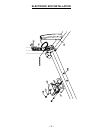
STEP #7 – ELECTRONIC BOX INSTALLATION
If installing optional PHL-60, see PHL-60 instructions for Electronic Box Installation. If not installing optional PHL-
60, follow instructions below:
1. Place Electronic Box Locating Board (76) behind Back Base Rail (13). Pull Base Rail Wire Harness (143)
through the Electronic Box Locating Board (76). Align Electronic Box Locating Board (76) with pre-drilled
holes in the Back Base Rail (13). Secure with two of each bolt #106, flat washer #133 and lock nut #128.
2. Place Electronic Box (77) onto Electronic Box Locating board (76). Plug wire harness (143) into Electronic
Box (77) so that the indicating lights are upwards and the plug is facing backward. Push excess wire into
Back Base Rail (13).
3. Install Protective Cover (78) and secure with two screws #121.
4. Plug one end of the power supply into wall receptacle and the other end into the Electronic Box (77).
The indicating lights of the Electronic Box (77) should blink green, showing there is power to it. When
sensors are activated, a steady red light will also come on.
Note:
Rear Cover For Optional Weight Stack (151) will only be used if PHL-60 is installed. If PHL-60 is
being installed, attach the Rear Cover for Optional Weight Stack (151) using the following instructions:
1. Install Rear Cover Link Plate (154) by aligning holes with Back Base Rail (13) and secure with bolt #112,
two flat washers #136 and lock nut #130.
2. Place the Rear Cover For Optional Weight Stack (151) so that the upper holes align with the holes in the
Back Top Rail (11). Secure with bolt #112, two flat washers #136 and lock nut #130.
3. Secure bottom portion of Rear Cover (151) to the Link Plate (154), using bolt #113, two flat washers
#136 and lock nut #130.
--5--


