


8
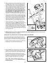
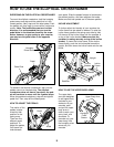
9. Make sure that all parts of the elliptical crosstrainer are properly tightened. Note: Some hardware may
be left over after assembly is completed.
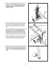
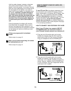
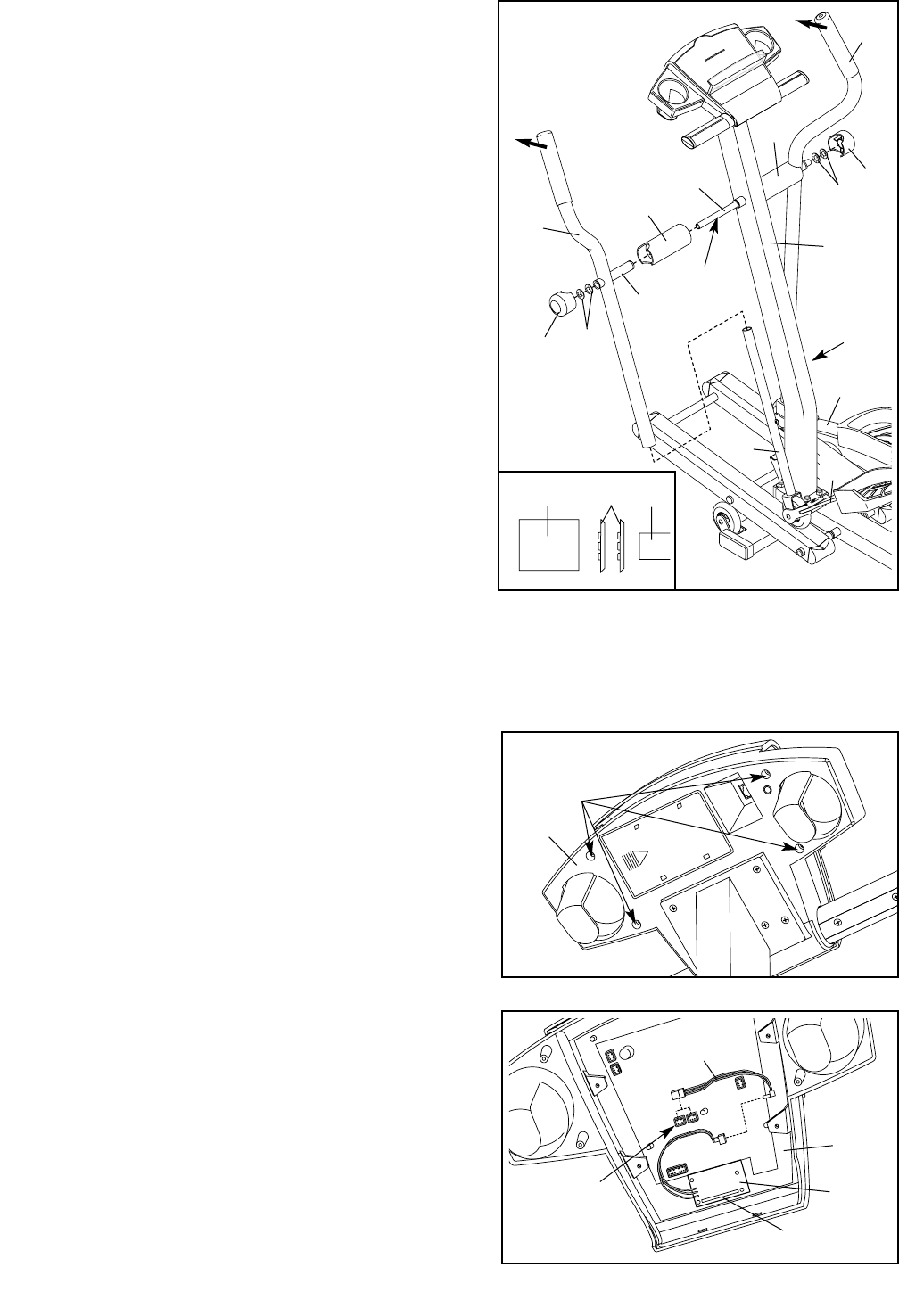
8. Apply a small amount of the included Teflon
®
lubricant
to a paper towel. Rub a thin film of the lubricant onto
the Chrome Tubes (21) on the Left and Right Spring
Arms (3, 4). Next, slide the Left Upper Body Arm (7),
which is marked with a sticker, onto the Chrome Tube
on the Left Spring Arm. Slide the Right Upper Body
Arm (75) onto the Chrome Tube on the Right Spring
Arm. Make sure that the Upper Body Arms are on
the correct sides—the upper ends should bend in
the direction shown by the arrows. Next, slide an
Axle Cover (74) onto the post on each Upper Body Arm.
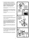
Apply grease to the Arm Axle (19). Insert the Arm Axle
into the right Axle Cover (74) and the Right Upper Body
Arm (75). Next, insert the Arm Axle into the Upright (2)
until the left end of the Arm Axle is flush with the left
side of the Upright. Then, insert the Arm Axle into the
left Axle Cover (74) and the Left Upper Body Arm (7).
Center the Arm Axle (19). Using the included pedal
tool, tap two Push Nuts (15) about 1/8” onto each end
of the Arm Axle. Make sure that the Push Nuts are
turned as shown in the inset drawing. (Note: It may be
helpful if another person holds a block of wood against
one end of the Arm Axle while you tap Push Nuts onto
the other end.) Then, press an Axle Cap (34) onto each
end of the Arm Axle.
8
21
21
2
74
Post
Grease
74
19
34
34
15
15
7
4
75
Pedal Tool 15 19
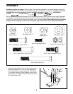
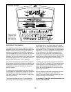
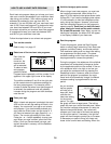
INSTALLING THE RECEIVER FOR THE OPTIONAL CHEST PULSE SENSOR
If you purchase the optional chest pulse sensor (refer to
page 20), follow the steps below to install the receiver and
the short jumper wire included with the chest pulse sensor.
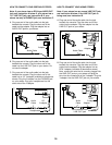
1. Remove the four indicated screws from the back of the
Console (87). Lift off the front of the Console.
2. Peel the paper off the adhesive pad on the back of the
receiver (A). Orient the receiver exactly as shown, and
press it onto the Console (87) in the indicated location.
Connect the short jumper wire (B) to the wire on the
receiver (A). Plug the other end of the short jumper wire
into either of the indicated jacks on the Console (87).
Note: The included long jumper wire is not needed.
Refer to step 1 above. Reattach the front of the
Console (87) with the four screws. Make sure that no
wires are pinched.
A
87
Jacks
87
Screws
1
B
Cylinder
2
3