


7
3
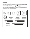
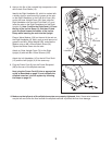
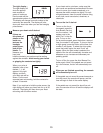
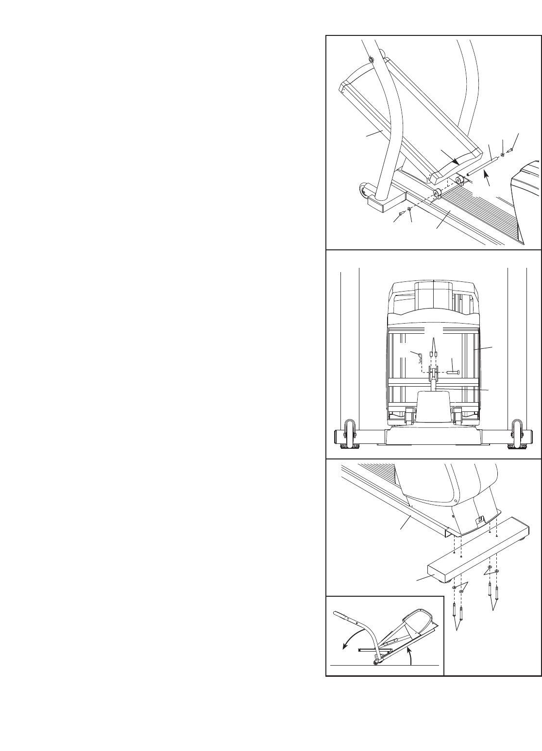
3. Slide an M8 x 28mm Washer (99) onto an M8 x 20mm
Button Screw (113). Tighten the Button Screw into one
end of the Incline
Axle (40). Apply a small amount of
the included grease to the Incline Axle.
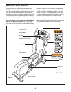
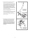
Orient the Incline Ramp (5) so that the straight end is
in the position shown. Hold the welded tube on the bot-
tom of the Incline Ramp between the two rings on the
top of the Frame. Insert the Incline Axle (40) through
the rings and the welded tube.
Slide an M8 x 28mm Washer (99) onto an M8 x 20mm
Button Screw (113). Tighten the Button Screw into the
open end of the Incline Axle (40).
Be careful not to scratch the Incline Ramp (5) during
steps 4 through 6.
113
5
99
113
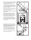
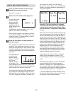
4. Using your fingers, turn the shaft on top of the Lift
Motor (42) counterclockwise until it stops turning.
Position the U-bracket on the bottom of the Incline
Ramp (5) over the end of the shaft as shown. Next,
hold an Incline Motor Spacer (60) on each side of the
shaft, between the shaft and the U-bracket.
Next, insert the Short Clevis Pin (118) through the U-
bracket on the Incline Ramp (5), the shaft on the Lift
Motor (42), and the two Incline Motor Spacers (60).
Insert the straight end of a Hairpin (71) into the end of
the Short Clevis Pin.
118
60
42
Front View
5
71
4
40
99
Grease
1
Straight
End
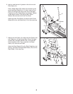
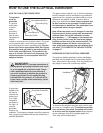
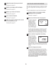
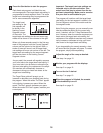
5. See the inset drawing. While another person tips the
elliptical exerciser as shown, place a sturdy piece of
packaging foam beneath the elliptical exerciser. Have
the other person continue to hold the elliptical
exerciser to steady it during this step.
Orient the Rear Stabilizer (2) so that the holes are
closer to the front. Attach the Rear Stabilizer to the
rear of the Frame (1) with four M8 x 68mm Button
Screws (1
10) and four M8 Split W
ashers (101).
Carefully remove the piece of packaging foam and tip
the elliptical exerciser back down.
5
1
110
110
101
2