


9
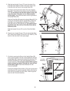
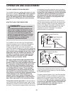
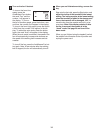
9. Remove the knob from the pin. Make sure that the collar
and the spring are on the pin.
Press the Latch Insert (77) into the left side of the Upright
Base (85) as shown. Use a rubber mallet if necessary.
Insert the pin into the Latch Insert. Tighten the knob back
onto the pin.
77
9
Knob
85
Pin
Collar
Spring
10.Make sure that all parts are properly tightened before you use the treadmill. Keep the included allen
wrench in a secure place. The allen wrench is used to adjust the walking belt (see page 27). To protect the
floor or carpet from damage, place a mat under the treadmill.
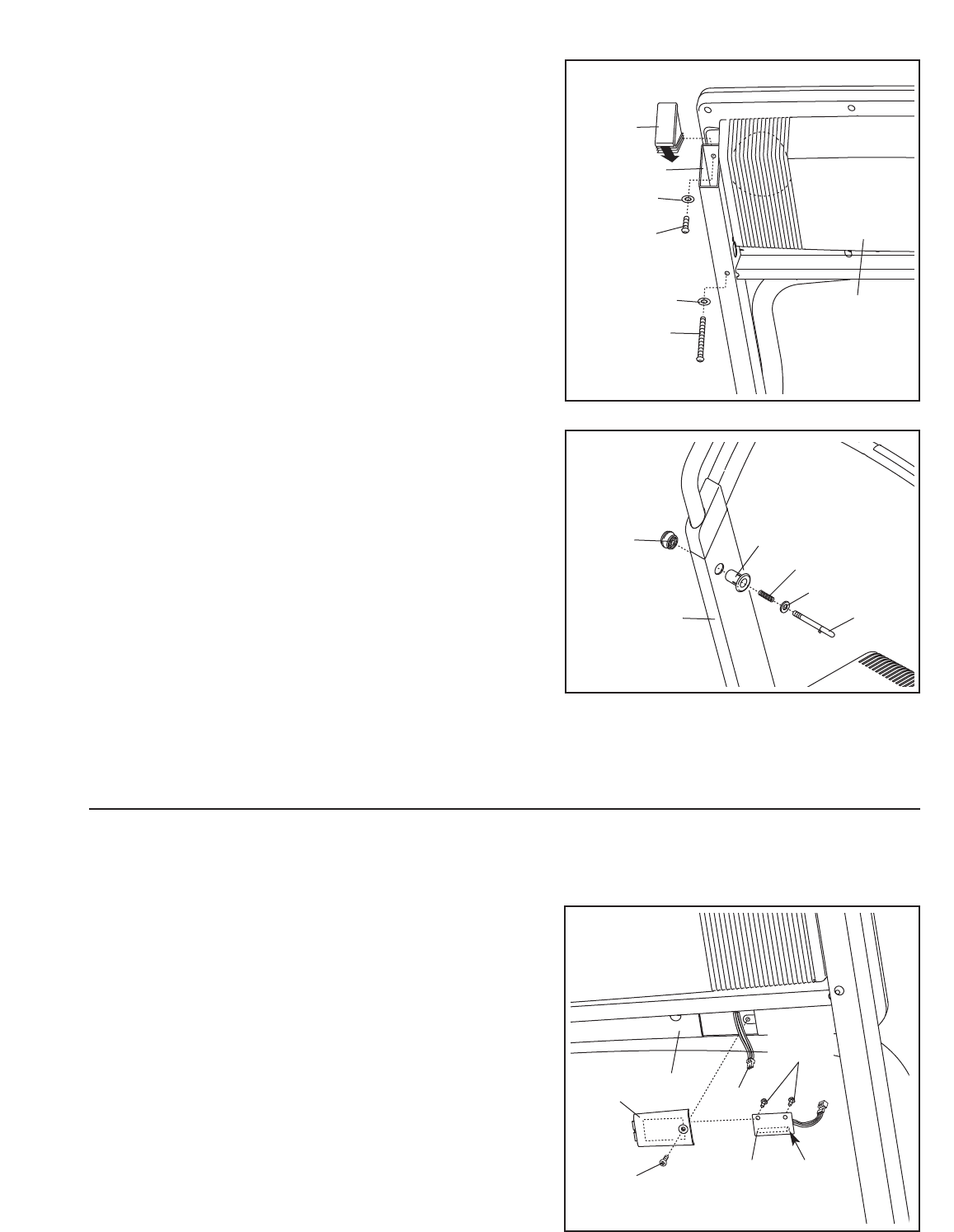
If you purchase the optional chest pulse sensor (see page 23), follow the steps below to install the re-
ceiver included with the chest pulse sensor.
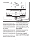
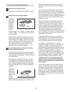
1. Make sure that the power cord is unplugged. Remove
the indicated 3/4” Screw (7) and the Access Door (95)
from the left side of the Console Back (96).
2.
Connect the wire on the receiver (A) to the indicated wire
extending from the Console Back (96).
Hold the re-
ceiver so the small cylinder is oriented as shown and
is facing the Console Back. Attach the receiver to the
plastic posts on the Access Door (95) with the two in-
cluded small screws.
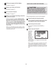
3.
Make sure that no wires are pinched. Reattach the
Access Door (95) with the 3/4” Screw (7). The other
wires included with the receiver may be discarded.
A
96
Small
Cylinder
7
95
Wire
Small
Screws
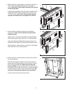
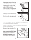
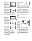
8. Set the console assembly on the Upright Base (85). Make
sure that no wires are pinched. Finger tighten a Console
Bolt
(72) with a Star Washer (67) into the lower hole in
each side of the Upright Base (only one side is shown).
Next, finger tighten a Short Console Bolt (112) with a Star
Washer (67) into the upper hole in each side of the
Upright Base (85) (only one side is shown).
Be careful
not to drop the Short Console Bolt into the Upright
Base. Firmly tighten all four Console Bolts.
Press an Upright Endcap (71), with the end indicated by
the arrow first, into each side of the Upright Base (85)
(only one side is shown). Use a rubber mallet if necessary.
112
85
67
67
72
71
8
Console
Assembly