


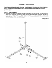

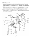
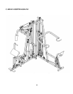
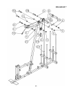
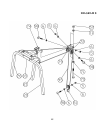
STEP 3 (See Diagram 3)
A.) Slide two ∅ 2 ½” Rubber Bumpers (#58) onto two Chromed Guide Rods (#58). Insert the two
Guide Rods into the holes on the Right Base Frame (#46). Slide the Selector Stem (#67) onto
the two Guide Rods (#22). Slide the Selector Stem over the Selector Rod (#69). Secure the
Selector Rod to the Selector Stem with two M10 x 1” Allen Bolts (#56). DO NOT install the
plates yet.
B.) Repeat the Procedure A above to install another set of Guide Rods.
C.) Place the Upper Frame (#8) over the two sets of Guide Rods then onto top of Right Vertical
Beam (#21) and Rear Vertical Beam (#50).
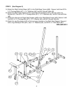
D.) Secure each set of Guide Rods (#22) to the Upper Frame with two M10 x 1” Allen Bolts (#56)
and ∅ ¾” Washers (#6).
E.) Secure the Right Vertical Beam (#21) to the Upper Frame with one Bracket (#7), two M10 x 2
¾” Carriage Bolts (#17), ∅ ¾” Washers (#6), and M10 Aircraft Nuts (#5).
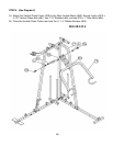
F.) Attach top of Left Vertical Beam (#77) to the Upper Frame. Attach the bottom of Left Vertical
Beam to the Left Base Frame (#87). Secure the bottom of Left Vertical Beam with two M10 x 2
¾” Carriage Bolts (#17), ∅ ¾” Washers (#6), and M10 Aircraft Nuts (#5).
G.) Secure the Left Vertical Beam (#77), Rear Vertical Beam (#50), and Upper Frame (#8) all
together with two M10 x 3” Carriage Bolts (#64), ∅ ¾” Washers (#6), and M10 Aircraft Nuts
(#5).
H.) Attach the Left Seat Support (#92) to the Left Vertical Beam (#77). Secure it with one Bracket
(#7), two M10 x 2 ¾” Carriage Bolts (#17), ∅ ¾” Washers (#6), and M10 Aircraft Nuts (#5).
Attach the other end of Left Seat Support (#92) to the Left Base Frame (#87). Secure it with
one M10 x 2 ¾” Carriage Bolt (#17), ∅ ¾” Washer (#6), and M10 Aircraft Nut (#5).
I.) Securely tighten all nuts and bolts previously installed.
J.) Carefully tilt the machine on its side. (Help of another person is a MUST.) Secure the four
Guide Rods (#22) to the Right Base Frame (#46) with four M10 x 1” Allen Bolts (#56).
K.) Attach the bottom of Leg Press Frame (#84) to the bracket on the Left Base Frame (#87).
Secure it with a M12 x 3” Allen Bolt (#89), two ∅ 7/8” Washers (#71), and one M12 Aircraft Nut
(#57).
L.) Attach a Leg Press Diagonal Support (#90) to each side of the Leg Press Frame. Secure them
together with two M10 x 2 ½” Carriage Bolts (#100), ∅ ¾” Washers (#6), and M10 Aircraft Nuts
(#5).
6