


ASSEMBLY GUIDE
F
J
B
J
G
D
H
A
E
M
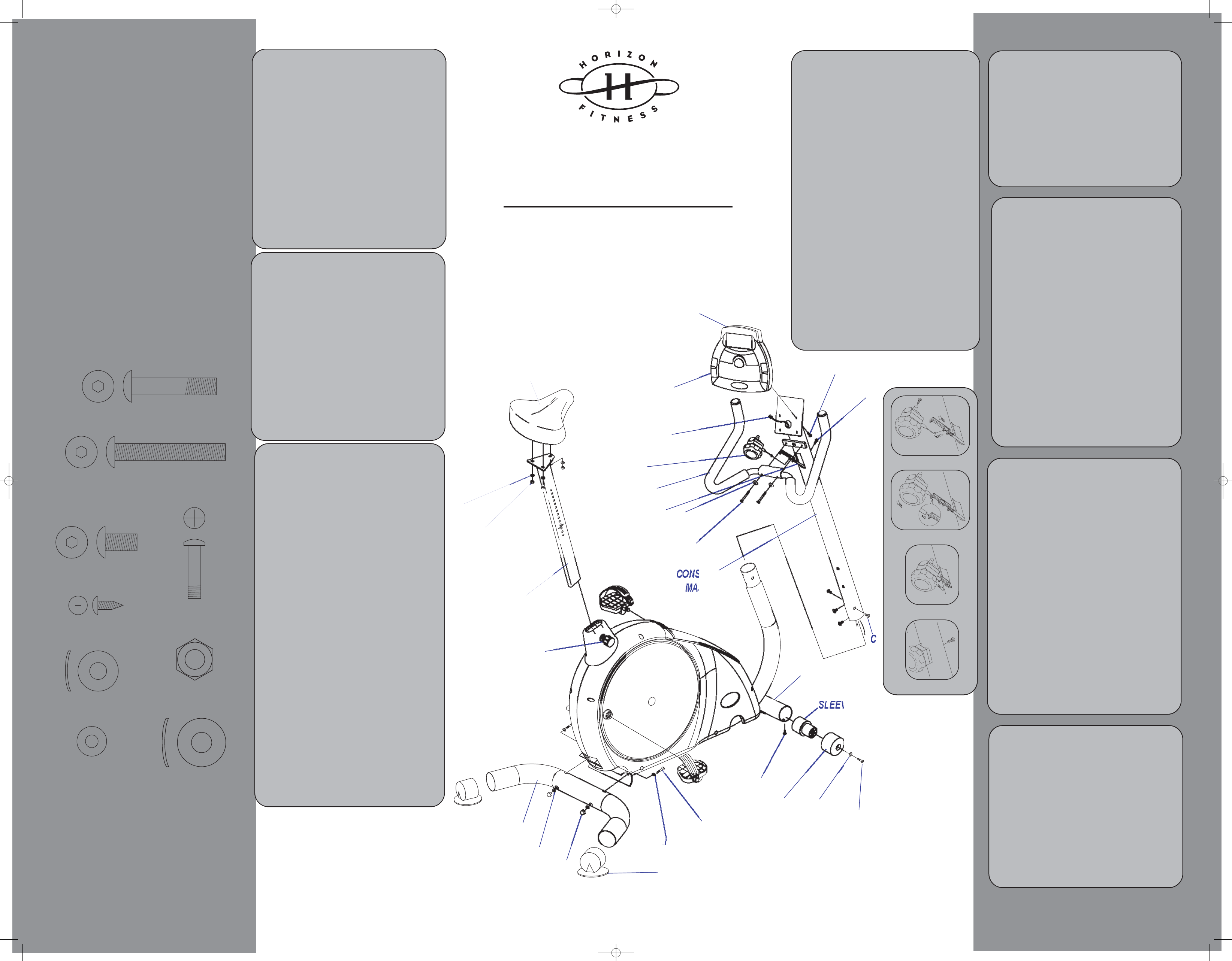
PEDAL
REAR FOOT TUBE
REAR FOOT PAD
POP PIN
SEAT POST
SEAT
GRIP PULSE
CONSOLE
CONSOLE DATA CABLE
HANDLEBARS
TENSION KNOB
TENSION KNOB
CABLE
FRONT TUBE
MOBILE WHEEL
SLEEVE
MOBILE WHEEL
SOLE
ST
I
L
K
UNPACKING
Unpack your Exercise Bike where you will be
using it. Place your bike on a level flat surface. It
is recommended that you place a protective cov-
ering on your floor. You will only need to attach
the following items. Verify that the following parts
and tools are included:
Parts
• 1 Rear Foot Tube
• 1 Handlebar Set
• 1 Seat Post
• 1 Seat
• 1 Console Mast
• 1 Console Mast Boot
• 2 Mobile Wheels
• 1 Console
• 2 AA Batteries
• 2 Pedals
• 2 Wheel Sleeves
• 1 Tension Knob
• 1 Hardware Pack (contents listed below)
E) 18mm Arc Washer
Quantity: 2
F) 14mm Washer
Quantity: 2
G) 20mm Bolt
Quantity: 2
D) 12mm screw
Quantity: 2
B) 90mm Bolt
Quantity: 2
C) 15mm Bolt
Quantity: 4
A) 45mm Bolt
Quantity: 2
Tools (included)
• 5mm Allen Wrench/
Phillips Screw Driver
• Flat Wrench
NOTE: It is recommended that you apply
grease to the threads of each bolt as you assem-
ble your Exercise Bike, to prevent loosening and
noise. Also, during each assembly step, ensure
that ALL nuts and bolts are in place and partially
threaded in before completely tightening any
ONE bolt.
STEP 4
Connecting the Tension Knob
a. Remove the 20mm long bolt (H)
on the back of the tension knob.
b. Turn the tension knob to level 15.
Connect the tension knob to the
bottom of the tension knob cable
(Figure A, Step 2).
c. Grasp the tension knob and firmly
pull the tension knob assembly
away from the machine in order to
attach to the top of the tension knob
cable (Figure B, Step 3). Make sure
that the copper cable end is seated
properly into the "key hole".
d. Insert the tension knob into the rec-
tangular opening on the console
mast (Figure C, Step 5).
e. Secure the tension knob with the
20mm bolt (H) by using a screw
driver (Figure D, Step 6).
STEP 1
Attach the Front Foot Wheels
a. Insert the wheel sleeves on each
side of the front wheel tube.
b. Align the holes in the wheel sleeves
with the holes in the wheel tube.
Insert two 12mm screws (D) and
secure with the screwdriver.
c. Attach the mobile wheels to the
wheel sleeves. Insert two 14mm
washers (F) and two 20mm bolts
(G) and secure with a screwdriver.
STEP 2
Attach the Rear Foot Tube and
Pads
a. Align the holes of the rear foot
tube with the holes in the base
frame.
b. Insert two 90mm bolts (B), two
20mm arc washers (J) and acorn
nut (H) secure with a 5mm allen
wrench.
c. Slide the rear foot pads to each
end of the rear foot tube.
STEP 8
Attach the Pedals
a. Thread the right pedal into the right
side pedal crank arm. Note: The
pedals are labeled on the end of the
threaded shaft for reference.
b. Tighten the pedal with the flat
wrench.
c. Repeat this process on the left side.
STEP 5
Attaching the Handlebars
a. Align the holes in the handlebars
with the holes in the console mast.
b. Insert two 45mm bolts (A) and two
washers (E) and secure with a
5mm allen wrench.
STEP 6
Attaching the Console
a. Open the battery cover on the
back of the console, insert two AA
batteries into the console and
replace the battery cover.
b. Connect the cables from the con
sole to the console cables running
through the console mast, mak-
ing sure that both ends snap togeth-
er tight.
c. Attach the console to the console
mast plate with the 15mm screws
(I). Secure using a screwdriver.
Note: Screws (I) are located on the
back side of the console.
STEP 3
Attaching the Console Mast
a. Unfold the console cable and the
tension knob cable, which is folded
into the console mast base.
b. Slide the console mast boot onto
the bottom of the console mast.
c. Slide the tension knob cable and
the console cable through the con-
sole mast. (Note: The tension knob
cable will only pull as far as the rec-
tangular opening in the console
mast. The console cable will need
to be pulled through the end of the
console mast.) To assist in pulling
the console cable and tension knob
cable through the console mast,
there should be a guide wire
attached to the top of the console
mast.
d. Insert the console mast into the
base, secure both sides of the
mast with four 15mm bolts (C)
using the 5mm allen wrench. Slide
the console mast boot into place.
STEP 7
Attach the Seat
a. Remove the three nuts (J) and
washers (K) from the bottom of the
seat.
b. Attach the seat to the seat post with
the three nuts (J) and washers (K),
securing with the flat wrench.
c. Loosen the pop pin by turning it one
or two revolutions, then pull the pop
pin mechanism to the outward
position.
d. With the pop pin in the outward
position, slide the seat post into
the base.
e. Release the pop pin and tighten to
the proper position.
Figure A
Figure B
Figure C
Figure D
6
5
4
3
2
1
CUSTOMER ASSISTANCE CENTER 1.888.993.3199 or www.horizonfitness.com
Hardware (Actual Size)
Express
1
1
0
0
0
0
J) 20mm Arc Washer
Quantity: 4
H) Acorn Nut
Quantity: 2
NEW Express 100 assembly guidev1.0.qxd 3/12/2003 4:05 PM Page 1