


P!N 3625336189
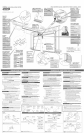
ASSEMBLY AND INSTALLATION POSTER
LiMiT SWITCHES
READ OWNER'S MANUAL COMPLETELY PRIOR TO [NSTALLATHON
RAIL STRAP/RAIL HEADER
FASTENEIRS* SHOWN FULL S_ZE
RAIL TO
POWER
TO WALL
Two #8 x 11/4" Pan Head Screws
not shown (Red bag)
TO CEIUNG
RAIL SECTION
CONNECTION
SlideCollarover long Nook
Mate Hooks
SHde Collar over Joint
Snap CHp behind Collar
d000a0
W[RE CUPS
DOOR ARMS
TO
H\x
\
\
\
DOORS MADE OF
MASONITE, UGHTWE_GNT
WOOD, F_BERGLASS, AND
ME]AL MUST BE
PROPERLY BRACED
BEFORE MOUNTING
3R OPENER. C(
DOOR MANUFACTURER
OR DISTRIBUTOR FOR
BRACING [NSTRUCT_ONSo
(SHORT AS POSSIBLE)
ARMS
(LONG AS POSSIBLE]
BASED ON THE HEIGHT
OF YOUR HEADER,
A MOUNTING BOARD
_4AY BE REQWRED
FOR ATTACHNG
HEADER BRACKET
DOOR BRACKET
TO DOOR ARMS
NOT INCLUDED
A1/4"-20 × 2" Carriage Bolt /4"-20 Hex Fmange Nut
WOODEN DOORS
>,
c
c_
E
o
LJ
_J
L0
GJ
_c
F=
<
J
c
_6
I
L_
_O
O
O
@
CONNECT RAK TO POWER HEAD
A Turn Power Head so that front panel (with end of shaft and rail
attachment flange} is facing up and place on a fiat [eve[ surface,
B Install Coupler on Motor Shaft (Figure 1),
• Place Coupler over end of shafLTurn it until it drops down over
• Lay Power Head on its bottom.
CAUTION
C Connect first Rail Section [with bearing (Figure 1)] to Opener Power
Head,
Slide Drive Screw so that bearing end extends several inches
out of rail.
Insert bearing end of Screw into Couplet
Slide Rai_into attachment flange and align holes.
Connect with 2 (1/4"_20) Hex Head Shoulder Bobs and 2 (1/4"
20) Hex Serrated Flange Nuts (Figure 2). Fingerotighten u_ti_
later.
Slide carriage stop into rail and up against the power head.
B
INSTALL RE_A[N_NG RAK SECTIONS
Arrange arrows on Rail Sections to point in same direction and away
from Power Head, (Middle rail same on both ends.)
Connect Screw sections:
- Push Middle Drive Screw out about 2" toward Power Head.
- %de Collar over Middle Drive Screw Hook (Figure 3A)o
- Turn Middle Screw by hand to align Drive Screw Hooks
between First and Middle Rail Sections.
- Latch two Hooks together and slide Collar over them
(Figure 3B) and (Figure 3C),
- Snap Clip on Drive Screw next to Collar (Fig_reSD).
Attach Middle Rail Section to First Ra][ Section, using 2 Rail damps,4
(5/16"ol 8) Hex Shoulder Bolts, and 4 (5/16"ol 8) Hex Head Serrated
Hange Nuts (Figure 3). Finger tighter _ti[ _ater.
NOTE
If a Rail Extension is needed, attach it now per the instructions
included with the Kit°
C Attach End Rail Section to Middle Rail Section foIbwing procedures
in Step A & B,
_NSTALL CARRIAGE
Hip Power Head / Rail Assembly upside down so that entire length
of the screw is visible,
Slide Carriage Assembly into sbt on End Rail Section with arrow
pointing away from the Power Head (Figure 4).
Power Head
Assembly
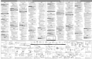
Figure I Instal[Couplerand 1stRailSection
Fig_ra 1 [nstaleel acopladory pdmero secci6nde baranda
Figere 2 Bolt 1st RailSectionto PowerHead
Figura 2 Cierrepfimero secci6nde barandaa [acabezade[ poder
B
ATTACH RAK STRAP TO [ND RAK SECTION
Attach Rail Strap to End Rail Section,
o Threaded stud of Rail strap should pass in front of end of RaiL
o Use 2 (5/16"o18) Hex Head Bolts and 2 (5/16" °18) Serrated Hange
Hex Nuts (Figure 5).
Tighten snugly but Do Not over4ighten,
AMGN RAK SECTIONS AND T_GHTEN ALL BOLTS
A Align all Rail Sections so Carriage Assembly can slide freely along
length of Rail
Securely tighte_ a[[ fasteners _owo Do Not overotig hten°
[ NSTALL AND CONNECT L_'aIT SWITCHES
CONECTEEL_ARANDALACAJADELMOTOR
A Voltee [acaja de[ motor hacia °bale y co[6queB en una superfide plan&
B InstaIe el acoplamiento en la flecha del motor (Fig_ra 1).
PRECAUTION
secdenesdel rid, Ha°tonga Bs Secdonesdd riel horizontales hastaqua el
abrepuertasde la puerta est_ensambBdo templet°me°tee
Turn Opener right side up.
B Hace Switches on Rail (Fig_reT)o (Switches are identicaL)
o Place one switch about 12"from Rail Strap end of Rail so that
the white trigger is toward Power Head, (Standing at Rail Strap,
looking toward Power Head, Switch wiJ[ be on Jeff side of RaiL)
This is the"CLOSE" Switcho
o Insert set screw into Switch and finger tighten only to
temporarily hem Switch in pbce.
o Connect Brown Wire to this Switch.
- Leaving a []tde slack in the Wire, run it down the groove in
top of Rail toward Power HeaG
Place remaining Switch about 12"from Power Head so that it
hangs on opposite side of Rail from first switch.This is the
"OPEN"Switch°
Insert set screw into Switch and finger tighten only to
temporarily hem Switch in place.
Connect Gray Wire to this Switch.
- Leaving a litde slack in the Wire, run it down the groove in
top of Rail toward Power Head.
C Coi_ remaining Wire on top of Power Head and tape down.
ATTACH EMERGENCY RELEASE CORD*
AND }(NOB
A Tie overhand knot at one end of emergency release cord and
pull cord through the hole in the rdease [ever up to the knot°
(Figiare 7).
Thread opposite end of cord through knob and tie a knot in this
end also,
C After installation of your garage door opener, adjust the
height of the knob to no less than 6 feet above the floor,
*The Emergency Release Cord is threaded through the Carriage
release [ever at the factory
C Ensamble la pdmera secci6n de[ rid a [a caja de[ motor de[ abrepuertas.
AtomiHe con 2 pernos con tope de cabeza hexagonal de (1/4"-20) y 2
tuercas de reborde hexagonal (1/4"o20) (Fights 2). Apriete manualmente.
Deslice la parada del coche en la baranda y contra el pode_ diringe.
[NSTALACiONDELAgSECCIONESADKIONALESDELA
A
B
Acomodelasflechasde[assecdonesde barandade maneraquatodas apuntenen [a
mismadirecci6ny haciaafuerade [acaiade[ motor.
° Conecte [as secci6nes de[ torni[[o.
- Saque el torniHo de transmisi6n intermedio aproximadamente
2"hacia B caja del motor.
- DesIice el collar sobre el gancho del tornilIo de transmisi6n
- Gire el torniHo intermed[o amane para alineaflo con los ganchos del
tornil[o de transmisi6n entre bs secciones primera e intermedia.
- Asegure dos ganchos juntos y deslice el collar sobre elias
(Fights 3B) y (Figura 3C).
- Cierre el clip sobre el tornillo de transmisi6n ceres del co%r,
Junte la secci6n intermedia de baranda con la pdmera secd6n, usando 2
abrazaderas de riel, 4 pernos de tope hexagonal (5/16"-I 8) y 4 tuercas de
reborde hexagonal (5/16"-18) en los per°as (Fights 3). Apriete
manualmente.
Sise requiere e[ ensamble Extensi6n (GSXL8), inst_le[o
siguiendo las instrucciones proporcionadas en el paquete,
C Junte la secd6n final de b baranda con b secci6n intermedia siguiendo ion
procedimientos descritos en los pasos A y &
Rai[gt_aD
Lacorreadelabaranda
Li_it Swit_:_es
ntem@tors
#8=32× °/8'
Wire ClOps
grapas
E_e_geit¢y Release K#ob
lape_Iladelaliberaci6n dela emergenca
............ RaN ¢[a_ps Retai_# 9 Clips
.. ..... L° abbrazadera de [a baranda E[dp que retiene
Ar_ws po_t toward doer _"
Lesfl_chesindiquentversB porte
Middle Rail
_® Section
Lasecci6n mad ana
dela baranda
Figure 3 Attach Middle RailSection
Fig_ra 3 Conectelasecd6n medianade baranda
_Bo EngageHooks
Comprometalosganchos
3CoSlideCollaroverHooks
Deslicecuello sobmganchos
°Do Snapon RetainingClip
Encajeapresi6oeldip querotone
Released Positio_
Toward door
a_d header
Hada puerta
T_ard Power Head Haciacabeza de poder
Figure4 Slide Carriageonto Rail
Figura4 Deslice[aAsambleade[ coche en Baranda
End Rail Section
La Secci6n Final de riel
Rail Stra
Correa de[ rie[
Figure 5 Attach Rail Strap
Fig_ra 5 Correa del rid
A
B
[NSTALEELENSA_BLEDELCORRED_ZOMA_N_TICOA
LASBARANDAS
Cobque [a[evade[ensambJedel corredizo en [a posici6n 'liberar".
Desliceel ensamb[edd corredizo en la ranura en lasecci6nfinal de barand con ia
punts de la flechadirigida en direcci6n opuesta a la cajade[ motor (Figura 4)_
BANDA DE BAR ANDA ALLASECdON FINAL
A Sujete[a bands del tie[ a lasecci6nfinal de[ rid usa°do 2 per nosde cabeza
hexagonal de (5/16"q 8)y 2 tuercas de reborde hexagonal (5/16"q 8) (Figura 5).
B Apriete firmemente cuidando no sobreapretados,
ALINEELAS$ECCIONE5DELABARANDAYAPRIETE
TODO$LOSPERNO$
A Alinee todas bs secdones de[ rid de maneraqua el ensamble de[ corredizo
mash@co pueda deslizarse[ibremente a1olargo de [a[ongitud de[ rieL
B Apriete firmemente todos lospemos cuidando no sobreapretados.
[NSTAL£ Y CONECTE LOS [NTERRUPTORS DE LOS
L_TE$ DE CJERR£ Y APERTURA
A
B
C
Gire al Operario boca arr]ba.
Co[oque swithces en [a baranda (Fights 5). flnterruptores son idTnticos.)
o Coloque un interrupter aproximadamente 12 pulgadas del fin de
correa de baranda de la baranda, pars que el disparador bbnco
estTn hacia la cabeza dd podero (Par_ndose en la correa de baranda,
mira°do la cabeza dd poder, el interrupter estara en el lade
izquierdo de [a baranda3 Esto es el interrupter CERCANG
o Meta el torniHo file en el interrupter y el dedo apt]eta para s61o
tener temporalmente el interrupter en el lugar.
o Conecte el alambre marr6n a este interrupter.
- Sa[]endo un pequeRo fleio en el alambre, Io corre abaio la
ranura en la cima de la baranda hacia la cabeza del poden
o Coloque el qued_ndose cambia aproximadamente 12 pulgadas
de la Cabeza del Poder para que cudgue en el bdo opuesto de
la baranda del primer interrupter. Esto es el interrupter ABIERTO
o Metala tripuIaci6n fija en el interrupter y el dedo aprieta
tener temporalmente el interrupter en el lugar.
Conecte el alambre gr]s a este interruptoro
- Sa[]endo un pequeBo fleio en el aIambre, Io corre °bale ranura
en la cima de B baranda hacia [a cabeza del poden
EnroJJeel remaiining alambre endma de [a cabeza de[ poder y 1ograba
hacia aba]o.
ASEGURELA_AN#A DELI_ERACIONDEB_ERGENG&,
Hags un medio nude en un extreme dela cuerda de [iberad6n de emergenda,
Ensarte el extreme opuesto de ]acuerda a travTs de la manila yen el
aguiero de JapaBnca de liberaci6n deJensamble del corredizo magnTtico
C Desputes de que la instalacion de su abridor de puerta de garaje,
adjusts la altura de la perilla a no menos de 6 pies encima del piso.
* La Cuerda de [a Liberad6n de [a Emergenda se enhebra por la
palanca de la liberaci6n del corredizo en la fZ_brica.
"CLOSE"
Brown Wi
"OPEN"
Gray Wr,
Figure 6 install Limit Switches on Assembled Rail
Fig_ra _ Instale los Interruptores de los Limites
E_e_ge_ey Release Tag
Leetiqueta dela Jiberad6nde
de emergent a
Emergency Release KHob
LaPerillade[a[ berac6n
de [aemergencia
F@_re 7 AttachEmergencyReleaseCord/KnobandTag
Fig_ra 7 ConectelaEmergendaCuerdade Liberaci6ny Etiqueta