


www.desatech.com
111487-01D 15
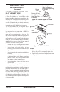
BURNER INJECTOR HOLDER AND
PILOT AIR INLET HOLE
The primary air inlet holes allow the proper amount
of air to mix with the gas. This provides a clean
burning flame. Keep these holes clear of dust, dirt,
lint and pet hair. Clean these air inlet holes prior to
each heating season. Blocked air holes will create
soot. We recommend that you clean the unit every
three months during operation and have heater
inspected yearly by a qualified service person.
We also recommend that you keep the burner
tube and pilot assembly clean and free of dust
and dirt. To clean these parts we recommend us
-
ing compressed air no greater than 30 PSI. Your
local computer store, hardware store or home
center may carry compressed air in a can. You
can use a vacuum cleaner in the blow position. If
using compressed air in a can, please follow the
directions on the can. If you don't follow directions
on the can, you could damage the pilot assembly.
Note: Removing the rear panel and top grates of
your stove will make cleaning easier.
1. Shut off the unit, including the pilot. Allow
the unit to cool for at least thirty minutes.
2. Inspect burner, pilot and primary air inlet
holes on injector holder for dust and dirt (see
Figure 20).
3. Blow air through the ports/slots and holes in
the burner.
4. Check the injector holder located at the end
of the burner tube again. Remove any large
particles of dust, dirt, lint or pet hair with a
soft cloth or vacuum cleaner nozzle.
5. Blow air into the primary air holes on the
injector holder.
6. In case any large clumps of dust have now been
pushed into the burner repeat steps 3 and 4.
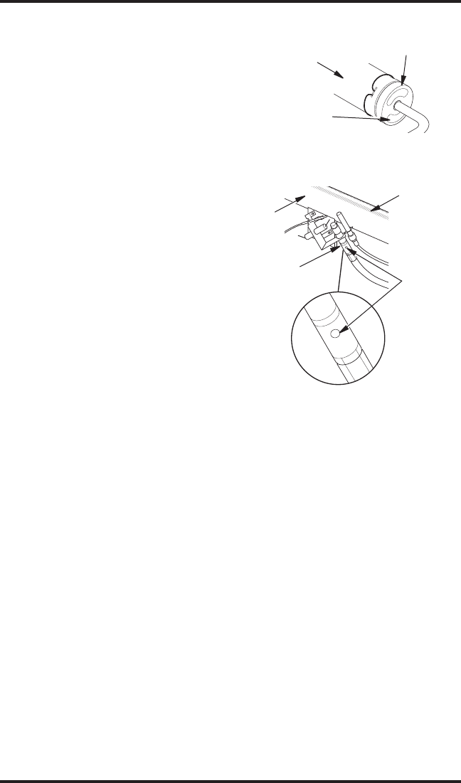
Clean the pilot assembly also. A yellow tip on the
pilot flame indicates dust and dirt in the pilot as
-
sembly. There is a small pilot air inlet hole about
two inches from where the pilot flame comes out
of the pilot assembly (see Figure 21). With the unit
off, lightly blow air through the air inlet hole. You
may blow through a drinking straw if compressed
air is not available.
CLEANING AND
MAINTENANCE
Continued
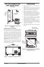
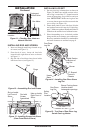
Figure 20 - Injector Holder On Outlet
Burner Tube
Burner
Tube
Injector Holder
(May Be Brass or
Aluminum Depending
on Model)
Primary Air Inlet
Holes (Shape of
Holes May Vary
by Model)
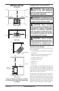
Figure 21 - Pilot Inlet Air Hole
Burner
Tube
Pilot
Assembly
Pilot Air
Inlet Hole
Ports/Slots
LOGS
• If you remove logs for cleaning, refer to Install-
ing Log Set, page 12, to properly replace logs.
• Replace log(s) if broken or chipped (dime-sized
or larger).