


CATEYE ADVENTURE
CYCLOCOMPUTER CC-AT200W
0678
ENG
U.S. Pat. Nos. 5236759/6957926 Pat./Design Pat. Pending Copyright© 2009 CATEYE Co., Ltd.
CCAT2W-090526
3
1
This device complies with Part 15 of the FCC Rules. Operation is subject to the following two condi-
tions:(1)This device may not cause harmful interference, and (2) this device must accept any inter-
ference received, including interference that may cause undesired operation.
Modifications
The FCC requires the user to be notified that any changes or modifications made to this device that are
not expressly approved by CatEye Co., Ltd. May void the user ’s authority to operate the equipment.
L mm
AC
SSE
MODE
MENU
MODE
+
SSE
MODE
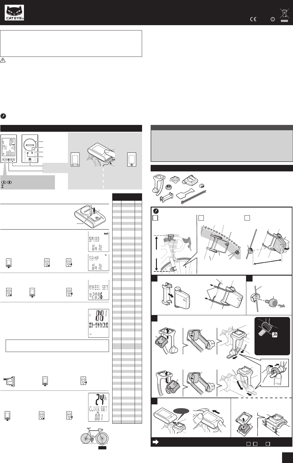
Tire circumference
reference table
ETRTO Tire size
L
(
mm
)
47-203 12x1.75 935
54-203 12x1.95 940
40-254 14x1.50 1020
47-254 14x1.75 1055
40-305 16x1.50 1185
47-305 16x1.75 1195
54-305 16x2.00 1245
28-349 16x1-1/8 1290
37-349 16x1-3/8 1300
32-369
17x1-1/4
(
369
)
1340
40-355 18x1.50 1340
47-355 18x1.75 1350
32-406 20x1.25 1450
35-406 20x1.35 1460
40-406 20x1.50 1490
47-406 20x1.75 1515
50-406 20x1.95 1565
28-451 20x1-1/8 1545
37-451 20x1-3/8 1615
37-501 22x1-3/8 1770
40-501 22x1-1/2 1785
47-507 24x1.75 1890
50-507 24x2.00 1925
54-507 24x2.125 1965
25-520 24x1
(
520
)
1753
24x3/4
Tubuler
1785
28-540 24x1-1/8 1795
32-540 24x1-1/4 1905
25-559 26x1
(
559
)
1913
32-559 26x1.25 1950
37-559 26x1.40 2005
40-559 26x1.50 2010
47-559 26x1.75 2023
50-559 26x1.95 2050
54-559 26x2.10 2068
57-559 26x2.125 2070
58-559 26x2.35 2083
75-559 26x3.00 2170
28-590 26x1-1/8 1970
37-590 26x1-3/8 2068
37-584 26x1-1/2 2100
650C Tubuler
26x7/8
1920
20-571 650x20C 1938
23-571 650x23C 1944
25-571
650x25C
26x1
(
571
)
1952
40-590 650x38A 2125
40-584 650x38B 2105
25-630 27x1
(
630
)
2145
28-630 27x1-1/8 2155
32-630 27x1-1/4 2161
37-630 27x1-3/8 2169
18-622 700x18C 2070
19-622 700x19C 2080
20-622 700x20C 2086
23-622 700x23C 2096
25-622 700x25C 2105
28-622 700x28C 2136
30-622 700x30C 2146
32-622 700x32C 2155
700C
Tubuler
2130
35-622 700x35C 2168
38-622 700x38C 2180
40-622 700x40C 2200
42-622 700x42C 2224
44-622 700x44C 2235
45-622 700x45C 2242
47-622 700x47C 2268
54-622 29x2.1 2288
60-622 29x2.3 2326
5
SENSOR
ZONE
5
4
5 mm
5 mm
SENSOR
ZONE
4
6
8
SENSOR
ZONE
SENSOR
ZONE
4 5
1
3
4
2
1
2
2
1
7
7
2
3
WARNING / CAUTION
Do not concentrate on the computer while riding. Ride safely!•
Install the magnet, sensor, and bracket securely. Check these periodically.•
If a child swallows a battery, consult a doctor immediately.•
Do not leave the computer in direct sunlight for a long period of time.•
Do not disassemble the computer.•
Do not drop the computer to avoid malfunction or damage.•
When using the computer installed on the bracket, change the • MODE by pressing on the four
dots below the screen, or by pressing on the SSE simultaneously, to start or stop the timer.
Pressing hard on other areas may result in malfunction or damage to the computer.
Be sure to tighten the dial of the FlexTight bracket by hand. Tightening it strongly using a •
tool, etc. may damage the screw thread.
When cleaning the computer, bracket and sensor, do not use thinners, benzene, or alcohol. •
A temperature sensor is built in the computer. If the sensor is heated by direct sunlight or •
body heat, it may not indicate the temperature correctly.
The altitude data with this unit is for reference only; accordingly, do not use this unit as a •
measuring device for professional use.
Dispose of used batteries according to local regulations.•
LCD screen may be distorted when viewed through polarized sunglass lenses.•
Wireless Sensor
In order to prevent any interference with the sensor signal, the transmission range is designed
to be 20 to 70 cm, in addition to use of the ID code. (This receiving range is only a reference.)
Please note the following points.
To use this unit, the sensor ID has to be set.•
Two different IDs, • ID1 and ID2, can be registered to this unit, which are identified automatically.
The computer cannot receive when the distance between the sensor and computer is too long. •
Temperature drop and battery drain may worsen the receiving sensitivity even if they are within
the transmission range.
Interference may occur, resulting in incorrect data, if the computer is:
Near a TV, PC, radio, motor, or in a car or train.•
Close to a railroad crossing, railway tracks, TV stations and/or radar base.•
Using with other wireless devices, or some particular battery lights.•
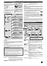
Before using the computer, please thoroughly read this manual and keep
it for future reference.
When using the computer for the first time or resetting to the factory
default setting, format according to the following procedure.
1
Format (initialize)
1. Press and hold the MENU button.
2. Press the AC button.
3. Release the AC button.
4. Release the MENU button.
2
Select the speed and temperature unit
When MODE and SSE are pressed simultane-
ously, “Speed unit” or “Temperature unit” can be
selected. Select “km/h” or “mph” for the speed
unit, and “°C” or “°F” for the temperature unit.
Press MENU to register.
3
Enter the tire circumference
Enter the tire circumference of your bicycle in mm.
Refer to the tire circumference reference table.*
4
Set the sensor ID
Hold the computer body close to the sensor (20
- 70cm), and press and hold the RESET but-
ton on the sensor with a sharp object. Sensor
will randomly generate an ID number for the
computer body to receive, and displays on the
screen. If successfully synchronized, screen will
automatically move on to Clock setting screen.
When setting the sensor ID, place the sensor at least 20 cm (approxi-*
mately 8 inches) away from the computer. Press and hold the RESET
button, the sensor will send the ID when releasing the button.
The computer is on standby for 5 minutes while setting the sensor ID. It dis-*
plays “ERROR”, and cancels the ID when no ID signal is received during the
standby, or you press MODE and SSE simultaneously. Screen will move on to
clock setting. Without the ID, speed cannot be detected and displayed. Be sure
to set the sensor ID according to “Sensor ID setting” on the menu screen.
Original ID is saved if you cancel the ID.*
5
Set the clock
When MODE and SSE are pressed simultane-
ously, “Displayed time”, “Hour”, and “Minute”
will appear, in this order.
Measure wheel circumference (L) of your bike
To get the most accurate calibration do a wheel roll out. With the valve stem
perpendicular to the ground, mark the pavement at the valve stem. With the
riders weight on the bike, roll the wheel one tire revolution in a straight line
and mark the ground when the valve stem is perpendicular to the ground
again. Measure the distance in millimeters. This is the most accurate wheel
calibration number.
How to restart
After changing the battery, or when the computer displays an error, restart the com-
puter according to the following procedure.
Press the 1. AC button on the back of the computer.
Set the clock. Refer to “Preparing the computer 5”.2.
The stored sea level altitude, home altitude, speed unit, wheel size, sensor ID, countdown dis-*
tance, selected wheel, AT setting, total distance and total altitude gain will not be changed after
pressing the AC button.
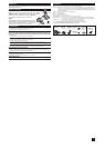
Preparing the computer
How to install the unit on your bicycle
1
Bracket band
2
Bracket
Nut
3
4
Sensor
5
Magnet
6
Sensor rubber pad
7
Bracket rubber pad
8
Nylon ties (x2)
5
8
7
1
6
4
2
3
AC
MENU
Unit
selection
Increase
the value
Move digits (By press-
ing simultaneously)
Register
the setting
Register
the setting
Register
the setting
(Finish)
Move to Clock
Setting when no
ID has been set
24h
↔
12h,
or increase
the value
Switch the screen
or move digits
(By pressing
simultaneously)
Switch the screen (By
pressing simultaneously)
Cancel the ID or
reset (By pressing
simultaneously)
Start the ID set-
ting (By press-
ing & holding)
MENUMENU
MENUMENU
MODEMODE
MODE
+
SSEMODE
+
SSE
MODEMODE
MENUMENU
MENUMENU
MODE
+
SSEMODE
+
SSE
MODE
+
SSEMODE
+
SSE
MODEMODE
Battery case cover
Pressure sensor
Press the SSE button with
the computer body together.
SSE button by itself does
not function.
Press only the computer
body.
Operation of buttons when the computer is
mounted on the bracket
km/h mph
: Speed unit
: Wheel size icon
: Sensor signal reception icon
MODE
+
SSEMODE
+
SSE
Click
RESET
Install the sensor and magnet
The clearance between
the sensor and mag-
net is 5 mm or less.
The magnet passes
through the sensor zone.
The distance from
the computer to the
sensor is within the
transmission range.
Sensor zone
Right front fork (inside)
The magnet may be installed anywhere on the spoke if the *
above installation conditions are satisfied.
Max
70 cm
A
Install the sensor
Right front fork
Install the sensor to the front fork as high as possible.*
Pull securely
Install the magnet
Spoke on the right
To the sensor zone
Attach the bracket to the stem or handlebar
When attaching the bracket to the stem
Stem
When attaching the bracket to the handlebar
On account of the receiving sensitivity, attach the *
bracket so that the computer is kept horizontal.
Handlebar
Click
While supporting it by hand,
For wing type handlebar or oversized stem, *
bracket can be mounted using the Bracket
Holder and nylon ties. (Option)
push it out as if lifting the front up
Cut
Caution:
Round off the cut edge
of the bracket band to
prevent injury.
B C
Remove/install the computer
After installation, check that the speed is displayed on the computer when gently turning the *
front wheel. When it is not displayed, check the positions of
A
,
B
, and
C
.