CABLE IN
CABLE OUT
Building
Wiring
Fault
RJ-45/
RJ-11
RJ-45/
RJ-11
RJ-45/
RJ-11
RJ-45/
RJ-11
CABLE IN
CABLE OUT
Building
Wiring
Fault
Phone or Fax
User’s Manual
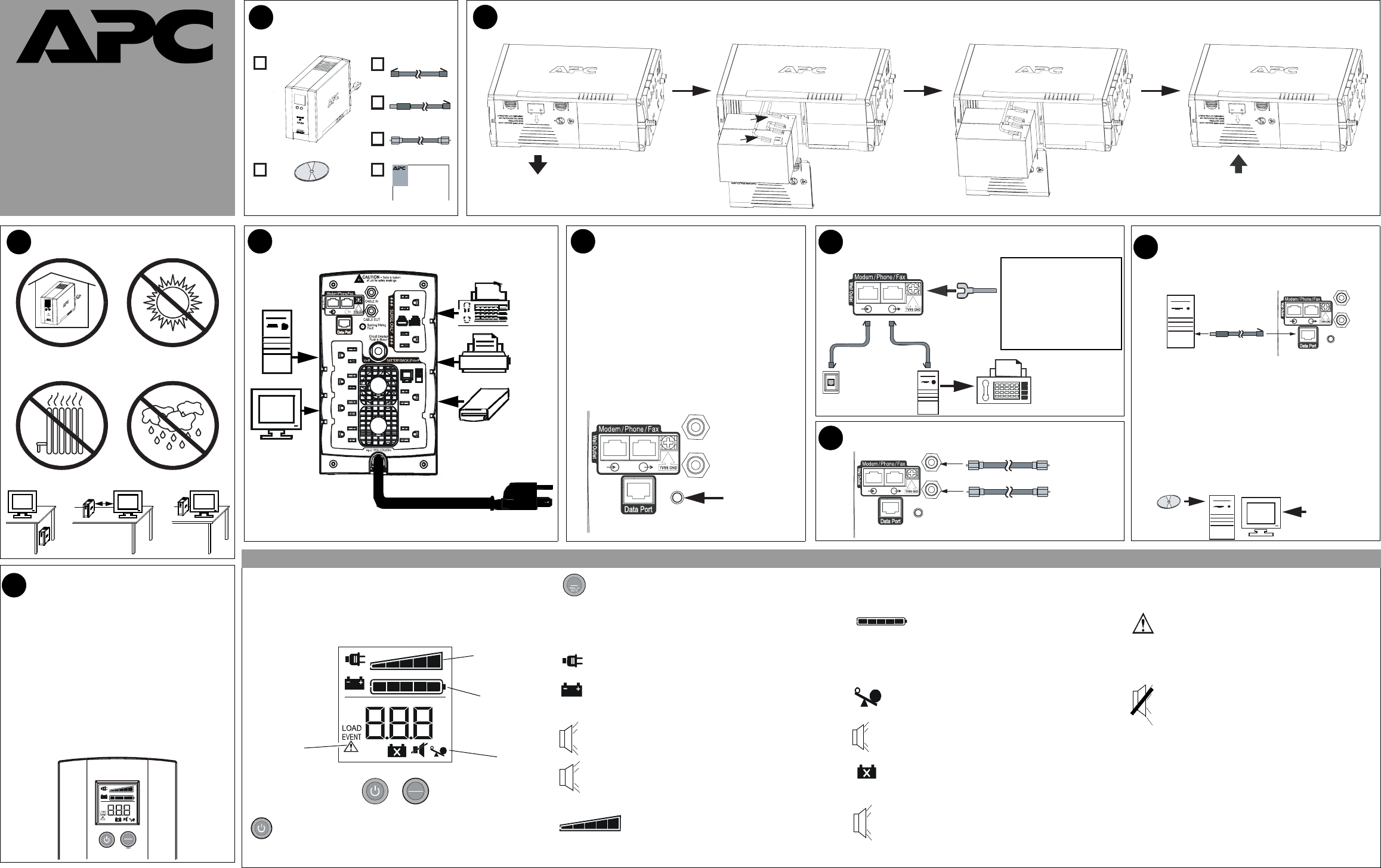
1
CONTENTS
2
3
CONNECT BATTERY CARTRIDGE*
OPERATING ENVIRONMENT
3
4
CONNECT EQUIPMENT / POWER
5
CHECK BUILDING WIRING
FAULT INDICATOR
6
7
CONNECT COAXIAL CABLES
The red, back lit liquid crystal display (LCD) on the front panel of the
Back-UPS displays realtime system status messages, system faults and
warnings, LOAD Capacity, and Battery Charge level. Two switches are
provided on the front panel, the power ON/OFF pushbutton switch on the
left, and the
DISPLAY/HOLD TO MUTE pushbutton on the right.
ON LINE - is lit whenever utility power is supplied to power
the equipment connected to the Back-UPS.
ON BATT - the On Battery symbol is lit whenever battery
backup power is used to power equipment connected to the
Back-UPS.
If the rear panel Building Wiring Fault (red) indicator is
lit, a potential shock hazard exists due to one of the
following conditions:
• Open or high resistance ground
• Hot and Neutral polarities are reversed
• Overloaded neutral circuit
Improper building wiring should be corrected by a
qualified electrician. Do not use the Back-UPS until the
condition that caused the fault is corrected.
Note: Improper building wiring will not prevent the Back-
UPS from operating, but it will limit its protection
capability.
32 - 104
o
F (0 - 40
o
C)
8
Back UPS
®
BR1300LCD
Back-UPS
®
BR1500LCD
Back UPS
®
BX1300LCD
Back-UPS
®
BX1500LCD
To 120 VAC Wall Outlet
Building Wiring Fault
Indicator
CONNECT MODEM/PHONE/Network
and TVSS Ground
From stand alone
data line surge
suppressor or
electronic device
Phone
Jack
Computer
Modem Port
OR
If needed, the Back-UPS features
a TVSS ground screw for
connecting the ground lead of
any additional stand alone surge
suppression devices, such as an
APC ProtectNet product; or any
electronic device with an
external ground connection.
Coaxial Cable
Coaxial Cable
From Cable
Provider
To Cable
Modem
To USB
Port
Æ
RJ-4
USB
RJ-45RJ-45
CoaxCoax
1
2
CONNECT DATA LINE AND
INSTALL SOFTWARE ON
COMPUTER (Optional)
CABLE IN
CABLE OU
Building
Wiring
Fault
RJ-45USB
1. Insert CD into computer, and on-screen instructions
should appear automatically. Follow instructions to
complete the installation.
Note: if the on-screen instructions do not appear
automatically (Autoplay is disabled), then
perform steps 2 and 3 below.
2. On the computer desktop of the display, double-click
on
My Computer.
3. Double-click on the CD-ROM drive icon, and follow
the on-screen instructions.
Installation of the supplied software is the only way to
take advantage of the auto shutdown capabilities that
Back-UPS offers.
To USB
Port
Follow the
on-screen
instructions.
9
SWITCH ON THE BACK-UPS
Note: Allow the Back-UPS to charge for a full 16 hours
prior to using it.
Press the front panel Power ON/OFF switch, and observe
that the following events occur after you press and release
the switch:
• The LCD turns on (is back lit).
•The ON LINE indicator flashes.
•The ON BATT indicator lights and flashes while a
self-test is being performed.
• When self-test has successfully completed, only the
ON LINE indicator will be lit.
• If the internal battery cartridge is not connected (see
Step 2 above), the ON BATT indicator will flash. The
Back-UPS will also emit a chirping sound.
Note: This diagram is also used for battery cartridge replacement.
Overload - is lit whenever power demand exceeds the
capacity of the Back-UPS.
It is displayed in both ON LINE
mode, and
ON BATT mode.
Continuous tone - this alarm sounds whenever the battery
backup outputs are overloaded. Overload mode is covered
in greater detail on Page 2.
Four Beeps Every 30 Seconds - this alarm sounds whenever
the Back-UPS is running on battery (
ON BATT). You should
consider saving any work in progress.
Continuous Beeping - this alarm sounds whenever a low
battery condition occurs, and battery run-time is very low.
Promptly save any work in progress, exit all open applications,
and shut down the operating system, computer,
LOAD
Battery
Charge
System
Faults
System
Status
Printer or Scanner
FAX
External Disk or
CD / DVD Drive
Computer
Monitor
RJ-11RJ-11
When lit, it indicates automatic voltage regulation
(AVR) is in “Boost mode”.
AVR is covered in greater
detail on Page 2.
Chirps for 1 Minute every 5 hours - this alarm sounds
whenever the battery fails the automatic diagnostic test.
Replace battery - this is lit whenever the battery is near the
end of its useful life, or if the battery is not connected. A
battery nearing the end of its life should be replaced.
2
w
w
w
.apc.com
®
However, when all five blocks are filled, the LOAD is at full
capacity. If the
LOAD exceeds the unit’s rated capacity, the Over-
load symbol on the bottom of the display will flash off and on.
Battery Charge - this indicator consists of a bar
with five blocks. When all five blocks are filled, the
battery is fully charged. When only one block is filled (lit) the
battery charge is low. The word
LOW and the Battery Capacity
indicator bar both flash off and on.
System Faults - when a fault occurs, this symbol
and the fault number (F01 - F09) will flash off and
on. The nine fault messages are described further on
Page 2.
Mute mode - the audible alarm (beeper) can be
muted (turned off), which is indicated by a line
through the beeper symbol. Mute mode is covered in
greater detail on Page 2.
AVR
Self-Test mode - can be run at any time when in ON LINE
mode
. Self-test is covered in greater detail on Page 2.
Sensitivity mode - this allows you to go into sensitivity
programming mode, and using the
DISPLAY button you can
select the
LO, MID or HIGH sensitivity range. Sensitivity
mode is covered in greater detail on Page 2.
Full Time Display mode - this mode allows you to set the
LCD to full time display mode using the
DISPLAY button.
This mode is covered in greater detail on Page 2.
Capacity
ON LINE
LOAD
IN
OUT
ESTIMATED RUN TIME IN MINUTES
V
Hz
SENSITIVITY
AVR
SEE MANUAL
LOW
ON BATT
%
kW
Power ON/OFF switch - is used to turn input power on and off.
It is also used to initiate self-test, to go into Sensitivity mode, and
it is used with the
DISPLAY button to reset the Event Counter.
DISPLAY/HOLD TO MUTE button - is used to display
status messages, system faults and warnings, and to perform
various operations, such as alarm mute mode,
AVR (auto-
matic voltage regulation), and full time display mode. The various
messages, warnings, system faults, and operations are described in
greater detail on Page 2.
Load Capacity - this indicator consists of a bar
containing five blocks. When only one or two of the
blocks are filled (lit), the unit
LOAD is at less than half capacity.
LOAD
30 cm
ONLINE
LOAD
IN
OUT
ESTIMATEDRUNTIMEINMINUTES
V
Hz
SENSITIVITY
AVR
SEEM ANUAL
LOW
ONBATT
%
kW
DISPLAY
HOLD TO
MUTE
DISPLAY
HOLD TO
MUTE
DIS PLAY
LCD INDICATORS and CONTROLS SUMMARY
Reset switch - this switch is located on the rear of the
Back-UPS, just above the fans, as shown in the figure in
Step 4.
990-4991
2


